background image

8

W100B.021014

Swegon reserves the right to alter specifications.

www.swegon.com/casa

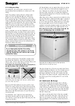
2.3 Ducts

Install the air ducts, sound attenuators, supply air diffus-
ers, air intake grilles and exhaust air ducts as shown in 
the ventilation drawings. To prevent the propagation of 
sound, do not install the ducts directly against structural 
building elements.

Insulate the air ducts according to the ventilation plan in 
order to reduce the losses of heat or cooling and to pre-
vent water from condensing on surfaces. The applicable 
fire resistance insulation requirements are also specified 
in the ventilation plan. 

It is of greatest importance to 

insulate cold ducts without gaps in the insulation, 
so that moisture cannot condense. 

2.4 To connect the cooker hood

The cooker hood is usually connected to the ordinary 
extract air duct. However the cooker hood can be 
connected to the ventilation unit’s separate extract air 
connection, in order to meet national regulations or for 
achieving a more effective than normal extract airflow. 
The duct between the cooker hood and the ventilation 
unit must be installed in such a way that makes it pos-
sible to clean it.

On delivery, the connection for separate extract air is 
blanked off.

If you connect the cooker hood to a separate ex-
tract air duct it is important to keep in mind that 
the airflow will then bypass the heat exchanger 
and this could cause an activation of the anti-
freeze protection function earlier than normal. 

Important

The bypass for a kitchen is intended for use 
when the airflows from the cooker hood/
kitchen are boosted. The kitchen’s general 
ventilation must take place via the extract 
air duct. If the general ventilation takes 
place continuously via the cooker hood, the 
supply air and extract air flows through the 
heat exchanger will be out of balance, and 
this will lower the efficiency and impair 
the ventilation unit’s anti-freeze protection 
functions during the winter.

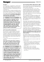
2.5 To seal around duct penetration collars

We recommend the use of a mounting frame designed 
for the ventilation unit (accessory) for sealing the vapour 
barrier in the loft ceiling beams.

Cut up the openings with approx. 10 mm smaller 
diameter than that of the ducts. Secure the mounting 
frame in the ceiling with screws through the holes on 
the sides. Tighten the plastic of the moisture barrier 
between the mounting frame and the structural ele-
ment of the building or fix it in position with tape tightly 
against the mounting frame.

It is also important to the preserve the tightness of the 
vapour barrier at the duct system’s other penetration 
collars that run through the attic joists. A building ele-
ment penetration seal (accessory) will facilitate this. This 
item is available in sets of 5 pieces, for diameters: 100, 
125 and 160 mm.

The thickness of the insulation and the nature of the 
surface layer of the ventilation ducts vary depending on 
insulation material, climate zone and national standards 
in force. For this reason, Swegon does not offer any 
recommendations. Most manufacturers of insulation 
material offer calculation programs for the calculation of 
sufficient and correct insulation.

In renovation projects, it is advisable to examine the 
existing ducts to determine whether they are sufficiently 
and correctly insulated. Insulating in the right way is 
necessary for the ventilation unit to operate correctly..

If 

the ducts are uninsulated, even across a small area, 
there is a high degree of risk of condensation and 
indirect damage.

The supply air and extract air ducts should be fitted 
with acoustic insulation along the stretch between the 
ventilation unit’s duct outlet and the sound attenuator, 
so that fan sound will not be propagated out into the 
room.

In general, ventilation ducts should be insulated in the 
following manner:

•  Insulate outdoor air ducts run through warm spaces.
•  Exhaust air ducts should always be insulated in ac-

cordance with national regulations. See separate 
project planning instructions (e.g.e ”Fire resistance 
requirements”).

•  Insulate supply air ducts in cold spaces.
•  Insulate extract air ducts in cold spaces.
•  If the air inside the duct is colder than in the sur-

roundings; the insulation should be protected by a 
vapour barrier.

Important

Check whether the ventilation unit has 
been supplied in the right-hand or left-
hand version to make certain that you are 
connecting the air ducts to the correct duct 
connection spigots on the unit. Check the 
ventilation plans to make sure that the 
duct connections are correctly installed.  
See also the dimensional drawings in the 
Section entitled: “Technical data”.

!

!

!

!

Summary of Contents for CASA W100B

Page 1: ...kig Montering drif och underh ll anvisning finns p adressen www swegon com sv Resurser Hitta PDF W100 En norskspr klig Montering drift og vedlikehold anvisning finnes p adressen www swegon com no Ress...

Page 2: ...2 7 Fan settings 10 3 2 8 Shutdown 10 3 2 9 Factory settings 10 3 2 10 Controllers 10 3 2 11 Functions 10 3 2 12 Electric air heater 11 3 3 Application 11 4 Servicing 12 4 1 Service reminder 12 4 2 T...

Page 3: ...t so that the fans have time to stop and air heaters if fitted have time to cool down There are no components inside the electri cal equipment cabinet that can be serviced by the user Leave the servic...

Page 4: ...minutes from a Premium control panel When the unit is controlled from a Premium cooker hood the fan s air flow boost time is 60 minutes You can select a damper open time of 30 60 or 120 minutes 1 3 F...

Page 5: ...ng can be reset by pressing a button inside the ven tilation unit The location of the button inside the air heaters is marked in the illustrations below When you press the reset button and feel it cli...

Page 6: ...the ventilation unit which on delivery is plugged 2 1 1 Wall mounting Mount the ventilation unit on a wall by means of a wall mounting bracket which is available as an accessory standard on the Duo m...

Page 7: ...ceiling mounting frame in ceiling anchor pieces with four size M8 threaded rods Adjust the length of rods so that they will extend no more than 30 mm below the inner surface of the ceiling mounting fr...

Page 8: ...of the ducts Secure the mounting frame in the ceiling with screws through the holes on the sides Tighten the plastic of the moisture barrier between the mounting frame and the structural ele ment of...

Page 9: ...buildings a control panel can be used as a so called hand held micro terminal in conjunction with service and installation work The connection of possible accessories is described in the wiring diagra...

Page 10: ...odels If the air heater s temperature drops to a risky level the Freeze risk alarm text will appear on the control panel display The air heater s freeze risk warning can be ac knowledged from the Free...

Page 11: ...a different way When preheating is In operation you can enter the following Required temperature limit value for the outdoor air supplied to the ventilation unit factory setting 20 C Overtemperature...

Page 12: ...ogged and clean them with a brush vacuum cleaner or running water as needed If you find it necessary to use detergent choose one that does not corrode aluminium Be careful not to damage the heat excha...

Page 13: ...on the model in the left hand version the components are mirror inverted 1 Extract air filter G3 2 Supply air filter PPI 20 3 Supply air filter F7 4 Plate heat exchangers 1 2 3 4 1 Extract air fan 2...

Page 14: ...rature decreases The overheating protection must be reset by pressing a push button on the air heater If you hear a click when you press in the button this indicates that the overheating protection ha...

Page 15: ...ng anti freeze protec tion sensor for water heated air heater 604919 2 Fan package ventilation unit R Model Supply air fan PWEC175L Extract air fan PEC119R Fan package ventilation unit L Model Supply...

Page 16: ...20 30 40 50 60 70 80 90 100 110 120 60 50 40 30 70 80 90 100 0 25 50 75 100 125 150 175 200 225 0 10 20 30 40 50 60 70 80 90 100 110 120 250 275 30 40 50 100 90 80 70 60 Thick line SFP 2 0 or lower 0...

Page 17: ...3 69 65 58 55 51 48 39 62 80 75 71 68 61 57 54 50 42 65 90 78 73 71 64 59 56 53 45 67 100 79 75 75 67 60 58 55 47 70 Fan setting Sound power level broken down into octave bands Lwokt dB Total assessed...

Page 18: ...ed sound power level LWA dB A 63 Hz 125 Hz 250 Hz 500 Hz 1 000 Hz 2 000 Hz 4 000 Hz 8 000 Hz 40 42 42 37 33 32 19 40 50 58 54 50 43 39 34 27 12 46 60 56 59 55 46 43 38 33 20 51 70 59 62 59 49 45 42 37...

Page 19: ...150 400 490 560 220 420 520 600 50 40 450 540 580 80 590 710 790 150 650 810 920 220 680 840 980 70 40 730 860 930 80 890 1070 1230 150 1000 1130 1410 220 1040 1280 1490 0 50 100 150 200 250 dm h 0 0...

Page 20: ...he heat exchanger 11 Door contact 7 6 2 Control functions with accessories Priority 1 Commands from outer sensor or the ventila tion unit s protective functions Priority 2 External supervision DDC Pri...

Page 21: ...0 Control priority 1 1 Fireplace switch 2 Boost timer 3 Humidity sensor 4 Timer 5 Sensor for negative pressure compensation 6 CO2 sensor with relay 7 CO2 sensor 8 Presence detector 9 Damper actuator f...

Page 22: ...trol Speed 1 1 2 9 VDC Speed 2 3 4 9 VDC Speed 3 5 6 9 VDC Speed 4 7 8 9 VDC Speed 5 9 max 24 V DC Control priority 3 0 0 9 V DC A1 A2 24VDC max 500mA Alarm output max 40V 500mA Close alarm Open no al...

Page 23: ...NUAL TIMER SWITCH Control of the fans and the cooker hood damper DESCRIPTION OF THE FUNCTIONS CONTROL FUNCTIONS The ventilation unit can be operated from a separate Premium control panel or a Premium...

Page 24: ...control panel or a Premium cooker hood When the ventilation unit is controlled from the cooker hood in the Home Away Boost modes and for local extraction the time can be set to 30 60 or 120 minutes T...

Page 25: ...ll mounting bracket and control panel W100 Premium Duo R right hand version PW100SRN L left hand version PW100SLN W100 Premium Duo Econo R right hand version PW100ERN L left hand version PW100ELN 7 11...

Page 26: ...eed 2 supply air fan 60 Speed 2 extract air fan 60 Speed 3 supply air fan 70 Speed 3 extract air fan 70 Speed 4 supply air fan 85 Speed 4 extract air fan 85 Speed 5 supply air fan 100 Speed 5 extract...

Page 27: ...for the ventilation unit Write down the data on the ventilation unit identification plate for reference when the need arises to contact a service company Preset by Date Important It is essential for c...

Page 28: ...observe the warning or installation instructions or investigation of such CHARGES DURING THE WARRANTY PERIOD The authorized service partner will not charge the client for repairs replaced parts repair...

Page 29: ...and that the following harmonised standards have been applied EN 60335 1 2002 A1 2004 A11 2004 A12 2006 A13 2008 A14 2010 A15 2011 A2 2006 EN 60204 1 2006 A1 2009 EN 60034 5 2001 A1 2007 EN 55014 1 20...

Page 30: ...30 W100B 021014 Swegon reserves the right to alter specifications www swegon com casa...

Page 31: ...W100B 021014 Swegon reserves the right to alter specifications 31 www swegon com casa...

Page 32: ...www swegon com casa...

Reviews: