CRM
c
Installation – Commissioning – Maintenance
20180327
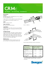
Figure 2.Straight duct length demands, see table below
.
Figure 1. Installation.
Accessories
Actuator:
Sauter ASM115SK005, ASM124SK002, 24 V AC, standard
actuators depending on size.
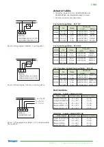
Other actuators must be ordered, see actuator table page 3.
Wiring diagrams are displayed on pages 2 to 3.
Knob:
CRTT-1 for manual control.
Quick connection:
FSR. Clamp with quick-acting lock.
Installation
Damper is Inserted into the connecting duct and fixed in
position by pop rivets or by means of an FSR clamp. See
Figures 1 and 2.
Commissioning
Connect hoses from a manometer to the measurement
nipples. Turn and lock the damper blade at the desired
setting angle For particulars of motorised control, we
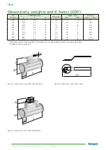
refer to the actuator supplier’s instructions. K-factors are
shown on the product’s identification label. The K-factor
can also be found in the table, page 4.
Maintenance
Clean the damper whenever needed by means of a
vacuum-cleaner or by wiping surfaces with a cloth.
Methodic Errors
Type of obstruction
upstream of the CRM
Length of straight duct (L)
upstream of the CRM
For m
2
= 5%
For m
2
=10%
One 90° bend.
3 x Ød
2 x Ød
Two 90° bends in the same
plane.
4 x Ød
2 x Ød
Two 90° bends in aligment at
right angles to one another.
4 x Ød
2 x Ød
One 45° damper.
6 x Ød
3 x Ød
One T-piece.
4 x Ød
3 x Ød
m
2
= methodic error B22, Building Research Council document
"Methods for the Measurement of Airflows in Ventilation
Installations"


