background image

GB.GOLDLP.170830

18     www.swegon.com

We reserve the right to alter specifications without notice.

15

10

20

15

20

25

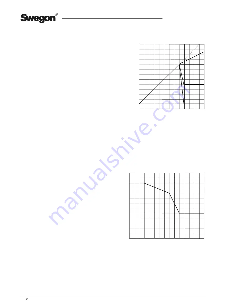
FRT-reglering 1

Extract air temperature °C

Supply air temperature setpoint

  °

C

Ste

p 1

Step 2

Breakpoint

EA-/SA dif

ferential

Step 3

Step 4

FRT-reglering 1

9.2.1.1 ERS Regulation

ERS regulation means Extract air temperature-Related 
Supply air temperature regulation. This means that the 
temperature of the supply air is regulated in relation to the 
temperature of the extract air. Under normal circumstanc-
es, the supply air temperature is regulated to be a few de-
grees lower than the extract air temperature. In this way, 
the heat exchanger will provide optimal performance, and 
this means excellent operating economy. ERS regulation is 
suitable for use when there is excess heat in the premises 
generated, for example, by machinery, lighting or people 
and the supply air devices in the premises are suitable dif-
fusing air below room temperature.

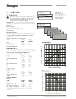
ERS REGULATION 1

The control unit regulates the relationship between the 
supply air and extract air temperatures according to a 
factory-preset curve.

See the chart to the right.

The steps, breakpoint and EA/SA differential plotted in 
the curve can be changed at USER LEVEL under TEMPERA-
TURE/SETTINGS.
Settings:

Value 

Setting  

Factory  

 range 

setting

Step 

1 – 4 

1

Breakpoint 

15-23 °C 

20 °C

(refers to extract air temp.)
EA/SA-Differential 

1-5 °C 

2 °C

The setting range for the breakpoint and EA/SA differen-
tial is limited by the Min. and Max. settings at 

INSTALLA-

TION LEVEL under HAND TERMINAL.

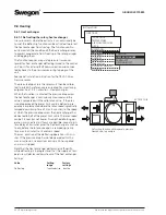
ERS REGULATION 2

This is used when special needs and conditions are such 
that the factory preset ERS regulation 1 curve cannot pro-
vide the results required. Conditional on which settings are 
made, it may be necessary to install a post-heating coil. 
An individually adapted curve regulates the relationship 
between the supply air and extract air temperature. 
See the chart to the right.
The following settings are possible at USER LEVEL under 
TEMPERATURE/SETTINGS:

Value 

Setting  

Factory  


range setting

Extract air temperature


X1 10-38 °C   15 °C


X2 11-39 °C   20 °C


X3 12-40 °C   22 °C

Supply air temperature setpoint


Y1 10-40 °C   20 °C


Y2 10-40 °C   18 °C


Y3 10-40 °C   14 °C

The setpoint displacement and summer night cooling 
functions can also affect the preset temperatures.

Breakpoints according to factory setting means:

If the extract air temperature is below 15 °C (X1) the set-
point for supply air temperature is constant 20 °C (Y1).
If the extract air temperature is 20 °C (X2) the supply air 
temperature set point will be 18 °C (Y2).
If the extract air temperature is above 22 °C (X3), the 
supply air temperature setpoint will be constantly 14 °C 
(Y3).

Factory setting means:

If the extract air temperature is below 20 °C (breakpoint), 
the supply air temperature setpoint will be automatically 
regulated to be 2 °C (EA/SA differential) lower.
If the extract air temperature is above 20 °C, the supply 
air temperature setpoint will follow the curve according to 
Step 1.

1

2

3

15

20

22

9

10

12

15

20

25

27

X = Extract air temperature °C

Y = Setpoint supply air temperature °C

ERS regulation 2

Summary of Contents for GOLD LP

Page 1: ... swegon com 1 We reserve the right to alter specifications without notice Operation and Maintenance Instructions GOLD LP Applicable to program version 3 04 and newer versions The document was originally written in Swedish ...

Page 2: ... 29 9 5 1 Switch clock 29 9 5 2 Extended Operation 29 9 5 3 Summer time Winter time 29 9 6 Heating 30 9 6 1 Heat exchanger 30 8 6 1 1 Defrosting the rotary heat exchanger 30 9 6 2 Pre Reheating 31 9 6 3 Heating BOOST 31 9 7 Cooling 32 9 7 1 Operation 32 9 7 2 Cooling Regulation Control 32 9 7 3 Periodic Operation 33 9 7 4 Regulation Speed 33 9 7 5 Outdoor Temperature Limit 33 9 7 6 Restart Time 33...

Page 3: ...S 0502 G except for the back side which con sists of aluminium zinc plated sheet steel The inner skin is predominantly made of aluminium zinc plated sheet steel The casing including the inspection panels has a 30 mm thick intervening slab of mineral wool insulation The GOLD LP is equipped with Class F7 bag filters DThe type RECOnomic rotary heat exchanger is variable speed controlled and has a pea...

Page 4: ... AIR Left hand version Supply air 3 Extract air fan with motor and motor controller 4 Pressure sensor extract air fan Position on function selector switch 1 5 Electrical equipm cubicle with control unit 6 Hand held Micro Terminal 7 Main switch Safety switch 8 Extract air filter 9 EXTRACT AIR Left hand version Outdoor air 10 SUPPLY AIR Left hand version Exhaust air 11 Supply air temp sensor to be m...

Page 5: ... unit has been switched off Risk areas with moving parts Typical moving parts are fan impellers and drive pulleys of the rotary heat exchanger Inspection panels can only be opened using a special key they therefore function as safety guards for fans and the heat exchanger If the ducts are not connected to the fan outlets the outlets must be fitted with a safety guard wire mesh screen Warning The i...

Page 6: ...ee Section 21 2 Commissioning record However in many cases these settings need to be adjusted to suit the current installation Program the switch clock operating conditions temperatures airflows and functions according to the procedures in Sections 5 16 Select whether l s m3 s or m3 h shall be used as the flow unit INSTALLATION LEVEL in the HAND HELD MICRO TERMINAL menu Fill out the Commissioning ...

Page 7: ...device A3 which means that you first throttle air device A4 the reference device to device A3 s ratio Thereafter the others are adjusted to the same ratio as air device A4 Throttle branch damper B to the same ratio as branch damper A throttle branch damper C to the same ratio as branch damper A Check that all dampers have the same ratio When the adjustment has been completed 3 air devices and one ...

Page 8: ...ure in the supply air section The pressure measurement tappings are situated by the junction hood Note that both pressure measurement tappings are used for measuring negative pressure MEASURED VALUES The negative pressure in the extract air section should be greater or the same as the negative pressure in the supply air section If the negative pressure in the extract air section is the same or up ...

Page 9: ...n and proceeds to next menu level ESCAPE reverts to the previous menu ADVANCE UPWARD or to the LEFT ADVANCE DOWNWARD or to the RIGHT DECREASES the value of the highlighted setting INCREASES the value of the highlighted setting 5 1 3 Display Screen The display screen has 4 lines Many of the menus howe ver have several lines and these are shown line for line as you press the ADVANCE DOWNWARD button ...

Page 10: ...NGS TEMPERATURE FLOW PRESSURE SWITCH CLOCK FILTERS AIR ADJUSTMENT ALARMS INSTALLATION AUTO OPERATION MANUAL LOW SPEED MANUAL HIGH SPEED SWITCH CLOCK TIME DATE TIME CHANNEL YEAR CHANNEL FILTERS READINGS CALIBRATION AIR ADJUSTMENT LOCKS FAN SPEED TIME SETTING 0 h ALARMS ACTIVE ALARMS ALARM HISTORY FLOW PRESSURE READINGS SETTINGS Important The appearance of the menus varies depending on the type of a...

Page 11: ...andling unit is started up for the first time a language selection menu is displayed Select the language desired If you want to change language at a later oppor tunity or if you ve selected the wrong language you can change the language at INSTALLATION LEVEL under HAND TERMINAL See Section 14 1 6 3 Changing Operating Mode You can start and stop the air handling unit or change over to manual or aut...

Page 12: ...reakpoint refers to 15 23 C 20 C extract air temperature ERS REGULATION 2 The control unit regulates the relationship between the supply air and extract air temperatures according to a custom plotted curve The curve has three adjustable breakpoints Settings see the chart to the right as well Value Setting Factory range settings Extract air temperature X1 10 40 C 15 C X2 10 40 C 20 C X3 10 40 C 22 ...

Page 13: ...h speed Low speed can be set to 0 which means that the fan is standing still HIGH SPEED Must always be preset The value or pressure for high fan speed cannot be lower than the value for low fan speed MAX SPEED Max speed is only appropriate for functions such as pres sure regulation Heating BOOST or Cooling BOOST The value for max fan speed cannot be lower than the value for high fan speed MIN MAX ...

Page 14: ...set at factory monitors the fan s speed increase conditional on the degree of fouling in the filter The calibration involves taking airflow and fan speed readings An alarm is initiated when the fan speed has increased by 10 above the preset alarm limit Filter monitoring with a pressure sensor accessory measures the pressure drop across the filter The alarm limit is preset in Pa 7 4 1 Readings When...

Page 15: ...initiated this is shown in the hand held ter minal both as clear text and by a blinking red diode This menu enables you to read alarms quickly ACTIVE ALARMS Shows alarms that are active but have not initiated an alarm signal in the display This applies to alarms that have a long delay i e airflow or temperature alarms ALARM HISTORY The 10 most recent tripped alarms are shown Alarm settings can be ...

Page 16: ...IDITY IQnomic Plus ALL YEAR COMFORT OPERATION TIME PROGRAMVERSIONS ALARM SETTINGS FIRE ALARM EXTERNAL ALARMS ALARM LIMITS ALARM PRIORITY HAND TERMINAL INST LANGUAGE AIR FLOW UNIT MIN MAX SETTING BASE SETTINGS COMMUNICATION EIA 485 ETHERNET SERVICE LEV CODE 0000 INSTALLATION 8 INSTALLATION LEVEL 8 1 Menu Survey FUNCTIONS TEMPERATURE AIR FLOW PRESSURE FILTER OPERATION HEATING COOLING HUMIDITY IN OUT...

Page 17: ...changer will have excess heat i e warm extract air giving it capacity to maintain the supply air tempera ture required As the supply airflow is regulated to a lower rate the air pressure in the premises will become negative and this will instead cause outdoor air to be sucked in through lea kage spots such as doors and windows This outdoor air will then be heated by the ordinary heating system of ...

Page 18: ...A differen tial is limited by the Min and Max settings at INSTALLA TION LEVEL under HAND TERMINAL ERS REGULATION 2 This is used when special needs and conditions are such that the factory preset ERS regulation 1 curve cannot pro vide the results required Conditional on which settings are made it may be necessary to install a post heating coil An individually adapted curve regulates the relationshi...

Page 19: ...es keeping a constant tempe rature in the extract air duct premises by regulating the supply air temperature This provides a uniform tempera ture in the premises regardless of the load and this type of regulation requires the installation of a reheating coil possibly a cooling coil as well The extract air temperature is measured by the tempera ture sensor inside the GOLD unit If this internal temp...

Page 20: ...setting Winter compensation Temperature displacement Y1 0 20 C 3 C Breakpoint X1 30 10 C 20 C Breakpoint X2 10 15 C 10 C Summer compensation Breakpoint X3 15 25 C 25 C Breakpoint X4 25 40 C 40 C Temperature displacement Y2 10 20 C 2 C X Outdoor temperature C X1 Y1 X2 X3 X4 Y2 Outdoor temperature compensation Winter compensation in accordance with factory setting involves Outdoor temperature 10 C B...

Page 21: ...mperature should be higher than the preset value The extract air should be at least 2 C warmer than the outdoor air The outdoor temperature should be above the preset value Heating has not been required between 12 00 23 00 hours The unit must not operate in the high speed mode or be stopped from an external source or manually from the hand held micro terminal Conditions to be met to stop summer ni...

Page 22: ...ing to start The unit should operate in a time channel switch clock stop The room temperature should be below set start tempe rature Conditions to be met for intermittent night time heating to stop High speed or external manual stop should be activated Room temperature should be above the preset stop temperature Alarm with preset stop priority has tripped If the needed the air handling unit fans w...

Page 23: ...nication Inactive External Outdoor Inactive IQnomic Communication Inactive Alarms 0 9990 min 5 min TEMPERATURE TEMPERATURE REG OUTDOOR TEMP COMP SUMMER NIGHT COOL INTERM NIGHT HEAT MORNING BOOST SETPOINT TEMP DISPL EXT SENSORS TEMPERATURE TEMPERATURE REG OUTDOOR TEMP COMP SUMMER NIGHT COOL INTERM NIGHT HEAT MORNING BOOST SETPOINT TEMP DISPL EXT SENSORS 9 2 6 Setpoint Temperature Displacement Used ...

Page 24: ... Sensor TBLZ 1 24 2 can be used both as a room sensor and an outdoor sensor They must therefore be addressed according to function using the function selector switch on the sensor The function selector switch must be in Position 1 if the sensor is used as a room sensor and in Position 2 if it is used as an outdoor sensor If the TBLZ 1 24 2 sensor is installed outdoors it must be mounted inside an ...

Page 25: ...speed This causes higher power consumption and may also cause discomfort in the form of noise 9 3 1 2 Pressure Regulation The airflow automatically varies to provide constant pres sure in the ducting This type of regulation is also called VAV regulation Variable Air Volume Pressure regulation is used when damper operations in crease the air volume in parts of the ventilation system The duct pressu...

Page 26: ...ion during the first energising occasion was not interrupted When the VOC sensor measures contents of emissions impurities that are lower than the preset value the air handling unit s supply air and extract air flows are then equivalent to the preset min flows When the VOC sensor instead measures contents of emissions impurities that are higher than the preset value the supply air and extract air ...

Page 27: ...sure is reduced The function has no effect if the airflow is demand con trolled The airflow is reduced as a percentage of the current airflow pressure Settings Value Setting Factory range setting Y1 max permissible reduction 0 50 30 X1 breakpoint 30 10 C 20 C X2 breakpoint 10 15 C 10 C AIRFLOW PRESSURE SA FAN REGULATION EA FAN REGULATION CLEAN AIR CONTROL OUTDOOR TEMP COMP SA DOWN REGULATION SLAVE...

Page 28: ...n be selected See Section 9 2 as well An adjustable temperature decrease allows a lower supply air temperature setpoint before down regulation begins This neutral zone can be set on line NZ SA DOWN REGU LATION in the appropriate menu Settings Value Setting Factory range settings Function Inactive SA SA EA Active Neutral zone 0 0 10 0 C 0 0 C 9 3 4 To adjust the flow of the slave fan It is possible...

Page 29: ... Low speed High speed 9 5 2 Extended Operation The inputs for external low speed and external high speed respectively can be supplemented with extended opera tion They can be used for overtime running activated by a pushbutton for example Desired time in hours and minutes can be set as follows Settings Value Setting Factory range settings External low speed 0 00 23 59 0 00 External high speed 0 00...

Page 30: ...hanger When the function is activated the pressure drop across the heat exchanger is continuously measured and the value is compared with the calibration value If the pres sure drop exceeds the preset limit value a defrosting se quence is implemented where the rotor speed is gradually ramped down ramp time of max 4 minutes to the speed at which the pressure drop across the heat exchanger has decre...

Page 31: ...p Pump pump valve valve Exercise period 1 60 min 3 min Interval 1 168 hrs 24 hrs 9 6 3 Heating BOOST Heating boost means that the air handling unit operating in the normal flow regulation mode increases both the supply airflow and the extract airflow in order to carry more heat into the premises The fans are allowed to work in the range between cur rent flows low speed high speed and preset max sp...

Page 32: ...ating the cooling demand for instance Connect to the IQnomic Plus module termi nals 15 16 On off 3 Steps Binary Used when cooling with two inputs controlled with three binary steps is connected Connect to the IQnomic Plus module Cooling relay 1 terminals 1 2 and Cooling relay 2 terminals 4 5 The cooling con troller of the unit regulates the cooling demand at 0 100 On an increasing cooling load Coo...

Page 33: ...d with pressure regu lation The flow increase takes place between current flow and preset max flow The function can be selected in five variants as follows Comfort The cooling outputs are activated if there is a cooling load When the temperature exceeds its setpoint and the sup ply air temperature is within the preset limit a regulated ramp function begins and increases the flow The control reacti...

Page 34: ...oil be mounted upstream of a postheating coil in the supply air duct see the example to the right The TBLZ 1 31 1 moisture sensor is mounted in the supply air duct and its cable is connected to the appropriate terminal on the GOLD unit Cooling energy is emitted to condense the moisture in the supply air flow which then is heated to the desired supply air tempe rature This causes a reduction in the...

Page 35: ...ling output 2 For controlling external cooling Inputs The control unit has two digital outputs terminals 5 6 and 7 8 They must be individually set to the function they are to have N B A maximum of two of the functions below can be combined as standard The number of combinations can be increased to four using the TBIQ IQnomic Plus module accessory See separate instructions Optional functions Extern...

Page 36: ...ice INSTALLATION FUNCTIONS FUNCTIONS TEMPERATURE AIR FLOW PRESSURE FILTER OPERATION HEATING COOLING HUMIDITY IN OUTPUTS IQnomic Plus ALL YEAR COMFORT OPTIMIZE IQNOMIC PLUS 9 10 IQnomic Plus IQnomic Plus is a name given to additional modules for extra control functions See special instructions ...

Page 37: ...20 Outdoor comp Cool water Active Inactive Inactive Outdoor temp X1 C 40 40 C 10 Cooling water Y1 C 5 30 C 22 Outdoor temp X2 C 40 40 C 20 Cooling water Y2 C 5 30 C 18 Outdoor temp X3 C 40 40 C 25 Cooling water Y3 C 5 30 C 14 Room comp Heating water Active Inactive Inactive Room temperature C 0 40 C 21 P band C 1 10 C 5 Night blocking Active Active Inactive Room comp Cooling water Active Inactive ...

Page 38: ... 12 OPTIMIZE The OPTIMIZE function optimizes the GOLD unit s airflow rates for the connected WISE system See the special documentation for WISE INSTALLATION FUNCTIONS FUNCTIONS TEMPERATURE AIR FLOW PRESSURE FILTER OPERATION HEATING COOLING HUMIDITY IN OUTPUTS IQnomic Plus ALL YEAR COMFORT OPTIMIZE ...

Page 39: ...d micro terminal 10 1 3 Zero Point Calibration The pressure transducer of the unit is automatically cali brated This calibration is carried out 3 minutes after the unit has been stopped The text ZERO PT CALIBR is shown in the hand held micro terminal The fans cannot start while calibration is in progress 10 1 4 Anti frost Monitoring Function Air Heater for Hot Water The anti frost monitoring funct...

Page 40: ...an be read The operation times per 24 hour period are given under the OPERATION TIME menu 12 MANUAL TEST Note Manual test running can cause indoor com fort problems There is also risk of overloading the system The responsibility for discomfort and over load rests totally on the person who activates the function Manual test run can take place for testing the inputs and outputs fans and heat exchang...

Page 41: ...he resetting of alarms can be selected to occur manu ally or automatically INTERNAL FIRE ALARM The air handling unit s internal temperature sensors serve as fire protection thermostats An alarm is initiated if the supply air tem perature sensor registers more than 70 C or when the extract air temperature sensor registers more than 50 C If an external Extract air Room temperature sensor is connecte...

Page 42: ...ng the settings BASE SETTINGS 1 and 2 are two levels where the user him herself saves current settings and activates them when needed The two base settings can be used as a summer setting and as a winter setting of the air handling unit The values in INITIAL SETTING 1 and 2 saved in the internal memory can be transferred to the external MMC memory by entering SAVE SETTINGS EXTERNAL MEMORY The valu...

Page 43: ...ion about interfaces proto cols and configuration is available at www swegon com 15 1 EIA 485 Protocol and settings for EIA 485 is specified Settings Value Setting range Modbus RTU Address speed parity stop bits Metasys N2 OPEN Lon Works Exolinc 15 2 Ethernet Protocol and settings for Ethernet is specified Settings Value Setting range Ethernet MAC ID DHCP SERVER active or inactive IP ADDRESS stati...

Page 44: ...hange filters or at least twice a year Also inspect the air handling unit fasten ers that secure it to the false ceiling wall or floor 17 2 2 Filter Spaces The most appropriate time to clean the unit is when you change the filters 17 2 3 Heat Exchanger Check at least twice a year whether cleaning is necessary Cleaning can be done from the filter space The heat exchanger should above all be cleaned...

Page 45: ...f the fault cannot immediately be remedied Consider whether the air handling unit can continue to operate until the fault has been remedied Choose to block the alarm and or to change it from STOP to OPERA TION See Section 12 Alarm settings 18 1 1 A and B Alarms For particulars of type A alarm indication to output for Alarm Relay A Inp 1 and Inp 2 see also 9 9 For particulars of type B alarm indica...

Page 46: ...or is lack ing is not connected or is faulty an air heater for hot water is connected A 1 1 3 s A 6 7 SUPPLY AIR TEMP SENSOR DEFECTIVE EXTRACT AIR TEMP SENSOR DEFECTIVE The supply air extract air temperature sensor is not connected or is faulty A A 1 1 1 1 3 s 3 s A A 8 OUTDOOR AIR TEMP SENSOR DEFECTIVE The outdoor air temperature sensor is not connected or is faulty B 0 1 3 s A 9 NO COMMUNICATION...

Page 47: ...MP SENSOR DEFECTIVE Temperature sensor in extract air duct or room is not connected Internal bus 1 contact or is faulty or has been selected with communication Applicable if the External sensor extract air room or Intermittent night time heating function is selected A 1 1 3 s A 31 EXT OUTDOOR TEMP SENSOR DEFECTIVE Temperature sensor for outdoor temperature is not connected Internal bus 1 contact o...

Page 48: ...t if pressure trans ducers are connected has been more than 10 below its setpoint for more than 20 minutes B B 0 0 1 1 20 m 20 m M M 46 47 SA DUCT PRESSURE ABOVE SETPOINT EA DUCT PRESSURE ABOVE SETPOINT Pressure in supply extract air duct if pressure trans ducers are connected has been more than 10 above its setpoint for more than 20 minutes B B 0 0 1 1 20 m 20 m M M 48 49 SUPPLY AIRFLOW BELOW SET...

Page 49: ...transducer connected for the heat exchanger Applicable to the defrosting function only B 0 1 10 s A 62 71 NO COMMUNICATION TO I O MODUL NR 1 9 The air handling unit s control unit cannot establish correct communication with the connected I O module 1 9 B 0 1 3 s A 72 Correct communication can be established between the CPU circuit card and the control unit s I O processor A 1 1 30 s A 75 SUPPLY AI...

Page 50: ...otection for the connected electric air preheater has tripped or is not connected A 1 1 3 s M 95 PREHEATING BELOW SETPOINT The preheating temperature is below the preset set point for ERS and Supply air control or Min SA temp for Extract air control longer than 0 minutes A 1 1 20 m M 96 LOST SETTINGS An incorrect checksum for the backup file is obtained on reboot When an alarm is generated set val...

Page 51: ... WATER TEMP SENSOR I O 7 DEFECTIVE Obtained if the cooling water temperature sensor temp is not connected or is defective B 1 0 3 s A 111 HEATING WATER TEMP SENSOR I O 7 DEFECTIVE Obtained if the heating water temperature sensor is not connected or is defective A 1 0 3 s A 143 NO COMMUNICATION W OPTIMIZE The AHU control unit cannot establish correct com munication with OPTIMIZE B 0 1 10 s A 160 NO...

Page 52: ...essure across the filters has been calibrated 2 H EXCH CALIBRATION NOT EXECUTED The pressure across the heat exchanger was not calibrated after the function was activated for the first time Recurrent at 24 hour intervals The message will not be received after the pressure across the heat exchanger has been calibrated 3 SPARE 4 INCORRECT DIP SWITCH SETTINGS DIL switches on the control circuit card ...

Page 53: ...lide rail Clear service space A clear space of 500 mm open space must be provided in front of inspection panels on the inspection side or in front of the extra inspection panel on the long sides for changing the filters A clear space of at least 200 mm must be provided above the electrical equipment cubicle for opening its cover Electrical equipment cubicle GOLD LP A B1 B2 C D E F G H1 H2 I J K L ...

Page 54: ...ectrical equipment cubicle 20 2 1 Internal Connections Control unit Red Yellow Black Brown Blue Black Heat exchanger motor Rotation monitor sensor 32 36 V AC from transformer 18 V AC from transformer 24 V AC from transformer Temperature sensor outdoor air Temperature sensor extract air Pressure sensor extract air fan Pressure sensor supply air fan Sensor supply air temperature Communication hand h...

Page 55: ...an Blue Brown Blue Yellow Green Brown Supply air fan Yellow Yellow Transformer Cable 230 V power supply 230 control voltage output Power unit LP 05 LP 08 PE PE L1 L3 N L2 3A L N Cable 400 V power supply 230 control voltage output Yellow Yellow Transformer Extract air fan Supply air fan Yellow Green Black Brown Grey Yellow Green Black Brown Grey ...

Page 56: ...oad 500 mA 34 PWM input for Clean Air Control VOC sensor 35 Measuring zero GND 36 Output fixed power supply 10 V DC out 10 V DC to GND Max permissible load 20 mA 37 Input 0 10 V DC for demand controlled control of the airflow or set point displacement Air quality sensor Digital inputs terminals 5 8 are of extra low voltage type Ana logue inputs terminal 37 has an input impedance of 66 k Ω DIL sele...

Page 57: ... 5 wire 400 V 10 15 50 60 Hz 10 AT 20 3 2 Fans RATED DATA PER FAN Size 05 1 x 230 V 50 60 Hz 0 74 kW Size 08 3 x 400 V 50 60 Hz 1 0 kW 20 3 3 Electrical equipment cubicle One 2 pole 3A Automatic circuit breaker for 230V control current 20 3 4 Heat Exchanger Motor Step motor 3 phase 5 8 A 2A 50 V max 90 V The motor controls limit the output power to the value speci fied 20 3 5 Control Inaccuracy Te...

Page 58: ...nd risk reduction EN ISO 13857 2008 Safety of Machinery Safety distances from machinery to prevent hazard zones being reached by upper and lower limbs EN 60204 1 Safety of machinery Electrical equipment of machines EN 61000 6 2 3 Electromagnetic compatibility EN 61800 3 Adjustable speed electrical power drive systems The following other standards and specifications have been applied EN 1886 2007 V...

Page 59: ...t time set Other controls Settings time channels scheduling time switch clock Channel Operating mode Times Week day 1 Low High 2 Low High 3 Low High 4 Low High 5 Low High 6 Low High 7 Low High 8 Low High Settings year channel scheduling time switch clock Channel Operating mode Times Period 1 Inactive Stop High Low 2 Inactive Stop High Low 3 Inactive Stop High Low 4 Inactive Stop High Low 5 Inactiv...

Page 60: ... X4 C 40 0 Summer comp Y2 C 2 0 Summer night cooling X Inactive Active Inactive Active EA temp start C 22 0 EA temp stop C 16 0 Outdoor air temp stop C 10 0 SA Setpoint C 10 0 In oper time start hh mm 23 00 In oper stop hh mm 06 00 Intermittent night time heating X Inactive Active Inactive Active EA Room start C 16 0 EA Room stop C 18 0 SA Night setpoint C 28 0 SA flow m s Pa 2 SA flow m s Pa 0 0 ...

Page 61: ...emand contr high speed SA 50 EA 50 Clean Air Control X Inactive Active Inactive Active VOC sensor Analogue X Bus Analogue Bus VOC low speed 50 VOC high speed 30 Min flow m3 s 0 08 size 05 or 0 2 size 08 Max flow m3 s 0 53 size 05 or 0 74 size 08 Outdoor temp compen X Inactive Active Inactive Active Flow Winter compens Y1 30 End point winter X1 C 20 Start point winter X2 C 10 Down speed regulation ...

Page 62: ...me s 480 Cool min SA flow m s 0 1 Cool min EA flow m s 0 1 Neutral zone C 2 0 Cooling BOOST X Inactive Comf Econ Sequ Inactive Comf Econ Sequ Comf econ Econ sequ Comf econ Econ sequ Start limit SA temp C 3 0 Ramp time 2 5 Humidity Dehumidification control X Inactive Active Inactive Active Rel hum SA RH 50 Inputs Outputs Relay 1 A Alarm output 6 Relay 2 B Alarm output 6 Input 1 External low speed 7...

Page 63: ...emperature C 21 P band C 5 Night blocking Inact Active Inact Active Night comp Heating water X Inact Active Inact Active Temp comp C 2 Night comp Cooling water X Inact Active Inact Active Temp comp C 2 Night comp X Inact Active Inact Active Channel 1 Start Stop Weekday Inactive Channel 2 Start Stop Weekday Inactive Pump operation Heating water Outdoor temp Start C 15 Outdoor temp Stop C 18 Pump op...

Page 64: ...400 IQnomic Plus I O module Nr 0 Input Output X Inactive Active Inactive Active I O module Nr 3 Ext monitoring X Inactive Active Inactive Active If active function I O module Nr 6 Ext cooling X Inactive Active Inactive Active I O module Nr 7 All Year Comfort X Inactive Active Inactive Active I O module Nr 8 Booster air diffusers X Inactive Active Inactive Active I O module Nr 9 Preheating X Inacti...

Page 65: ...o Man Auto Time delay Alarm 2 s 10 Alarm on closure Alarm 2 1 Alarm reset X Man Auto Man Auto Alarm limit temperature Deviation SA setpoint 5 0 Min EA temperature 15 0 Filter function Filter alarm limit SA Pa 10 100 EA Pa 10 100 H EXCH defrosting Alarm limit Pa 50 Service period Alarm limit month 12 Alarm priority See the following pages Hand held micro terminal settings Language English Flow unit...

Page 66: ... Port nr 47808 The values by turns refer to sizes 05 and 08 1 0 2 03 m3 s 2 0 3 0 4 m3 s 3 0 53 0 74 m3 s 4 Only in combination with Cooling BOOST 0 53 0 74 m3 s 5 Only in combination with Demand control 0 08 0 20 m3 s 6 Possible options Control of outdoor air exhaust air damper in operation indication low speed operation indication indication or high speed operation group alarm A group alarm B co...

Page 67: ...t in EA frequency conv A 1 1 14 Under voltage in SA frequency conv A 1 1 15 Under voltage in EA frequency conv A 1 1 18 Excess temperature in SA frequency inverter A 1 1 19 Excess temperature in EA frequency inverter A 1 1 20 No communication SA frequency range gateway A 1 1 21 No communication EA frequency range gateway A 1 1 22 Hall sensor defective SA frequency range A 1 1 23 Hall sensor defect...

Page 68: ...1 56 No comm EA air flow pressure sensor A 1 1 57 No comm SA filter pressure sensor B 1 0 58 No comm EA filter pressure sensor B 1 0 59 No comm SA duct pressure sensor A 1 1 60 No comm EA duct pressure sensor A 1 1 61 No comm r hx pressure sensor B 1 0 62 No communication to I O module No 0 B 1 0 63 No communication to I O module No 1 B 1 0 64 No communication to I O module No 2 B 1 0 65 No commun...

Page 69: ...ective B 1 0 103 Heating valve I O 7 defective A 1 0 104 Cool circuit pump I O 7 tripped B 1 0 105 Heat circuit pump I O 7 tripped A 1 1 106 Cooling water temp I O 7 below set point B 1 0 107 Heat water temp l I O 7 below set point A 1 0 108 Cooling water temp I O 7 above set point 0 1 0 109 Heating water temp I O 7 above set point 0 1 0 110 Cooling water temp sensor I 0 7 defective B 1 0 111 Heat...

Page 70: ...o Overall efficiency ηe s Efficiency grade N Efficiency category Vaiable speed drive COMPACT Installation category GOLD LP GOLD SILVER C Version E RX PX CX SD Air Handling Units including GOLD E EU regulation 327 2011 fan data Technical documentation data Datum 2013 09 19 Impeller diameter Motor power Power input Ped Air Flow qv Pressure increase pfs Speed n mm kW Actual Req 2013 Req 2015 Actual R...

Page 71: ...3 58 Yellow Average NRVU BVU variable speed Other 81 0 34 0 42 647 1 6 300 148 59 3 48 Blue Max high NRVU BVU variable speed Other 79 0 49 0 67 1244 2 4 241 255 59 3 5 1 2170 52 Red Max low NRVU BVU variable speed Other 79 0 49 0 54 1463 2 4 0 255 59 3 52 Red Min low NRVU BVU variable speed Other 71 0 08 0 04 491 0 4 0 24 59 3 17 Red Min high NRVU BVU variable speed Other 71 0 08 0 54 164 0 4 994 ...

Page 72: ...GB GOLDLP 170830 72 www swegon com We reserve the right to alter specifications without notice All documentation is available in digital form and can be downloaded from www swegon com ...

Reviews: