background image

M

a

nual LU

N

A

 c R

E

 / LU

N

A

 b T

-C

U

7

 2009-05-22 

www.swegon.com

2.1 Jumper settings of the controller

The following pages describe different functions of 
the controller LUNA c RE. The controller can be con-
fi gured with jumpers and by settings in the memory 
that  can be confi gured with the confi guration  device 
LUNA b T-CU.

Be careful when handling the printed circuit board. 
Never touch anything while the power is on. Do not 
touch any components on the circuit board. The com-
ponents can be destroyed by an electrostatic discharge. 
If possible, use an ESD-wrist strap connected to pro-
tective ground. 

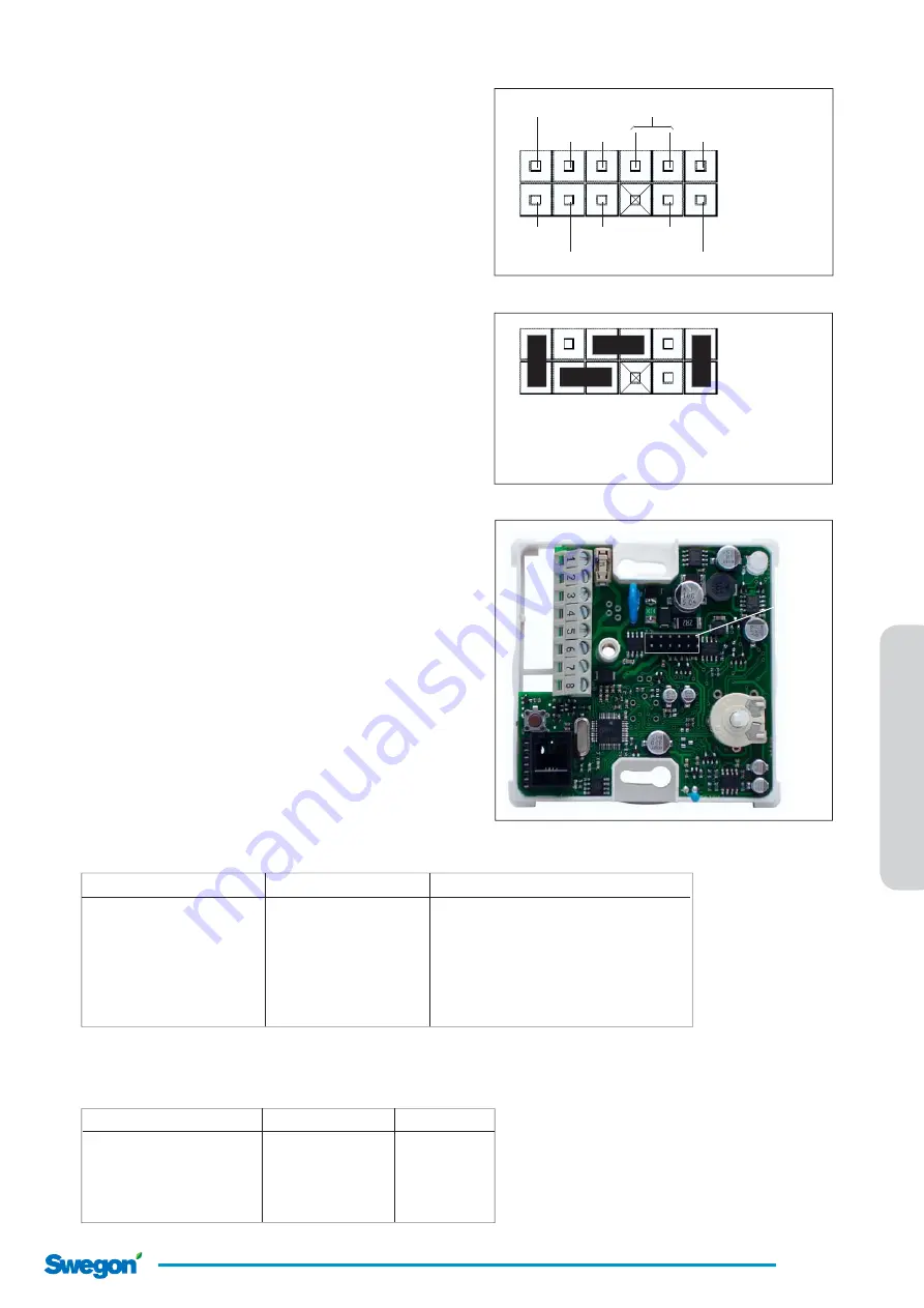
The pictures to the right show different signal, and 
functions of the jumper block, and also the standard 
confi guration.

Always check that you are looking at the circuit board 
with the correct orientation, by locating pin 1 on the 
jumper block J1 as shown on the picture to the right. 

All handling of the circuit board is done at your own 
risk!

Terminal 1

1

”A1”

In 2

Terminal 8

”d2”

”d1”

Terminal 7

Terminal 4

In 1

”A2”

Signals in jumper block ”J1”

In 1 = input 1
In 2 = input 2
D1 = digital out 1
D2 = digital out 2
A1 = 0-10V DC out
A2 = 0-10V DC out

Controller LUNA c RE circuit board

Pin 1

1

Standard jumper confi guration

Plint 1: 

Output ”d1” (cooling 24V)

Plint 4: 

Output ”d2” (heating 24V)

Plint 7: 

Input external sensor

Plint 8: 

Input condensation sensor

2.2 Input functions

Different types of sensors can be connected to the digi-
tal input 1 and 2. The table below shows the different 
combinations that can be activated in the controller 
with the confi guration unit. 

External temperature and condensation sensor

 is 

default setting from the factory. 
The column 

Deactivate 

shows what functions that 

has to be deactivated to avoid any collision with active 
functions.

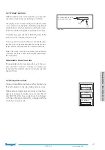
The table below shows where to fi nd input function menus 
in the controller, and descriptions of these in the manual. 

Function    

Menu 

Description

Occupancy   


6, Occupancy 

Chapter 3.18

External temp. sensor 

5, Inputs 

Chapter 3.17

Condensation  


” 

Operation mode override 

” 

Terminal 7 (in1)  

Terminal 8 (in2) 

Deactivate

Occupancy  Condensation 

-

Operation mode override 

Condensation 

Occupancy

External temp. sensor 

Condensation 

Occupancy, Operation mode override

Operation mode override 

Occupancy 

Condensation

External temp. sensor 

Occupancy 

Condensation, Operation mode override

External temp. sensor 

Operation mode override   Occupancy, Condensation

Summary of Contents for LUNA b T-CU

Page 1: ...Manual LUNA c RE LUNA b T CU 1 2009 05 22 www swegon com Manual v1 1 Manual for room temperature controller LUNA c RE and configuration device LUNA b T CU versions v1 10 v1 19...

Page 2: ...r and condensation sensor page 9 3 Configuration device LUNA b T CU 3 1 The configuration device in general page 11 3 2 Configuration device modes page 12 3 3 The buttons page 13 3 4 The display symbo...

Page 3: ...Manual LUNA c RE LUNA b T CU 3 2009 05 22 www swegon com 1 Room temperature controller LUNA c RE...

Page 4: ...n is activated and the controller s cooling output is activated 1 2 Function button The picture to the right shows where the function button is located It has the following functions Calibration of th...

Page 5: ...useful if there was an error trying to configure the controller etc Performing a memory reset 1 Switch off the power to the controller 2 Press and hold down the function button ans switch on the power...

Page 6: ...Manual LUNA c RE LUNA b T CU 6 2009 05 22 www swegon com 2 Jumper settings of the controller and input functions...

Page 7: ...digital out 2 A1 0 10V DC out A2 0 10V DC out Controller LUNA c RE circuit board Pin 1 1 Standard jumper configuration Plint 1 Output d1 cooling 24V Plint 4 Output d2 heating 24V Plint 7 Input externa...

Page 8: ...sensor Terminal 1 Output d1 cooling 24V Terminal 4 Output d2 heating 24V Terminal 7 Input external sensor Terminal 8 Input condensation sensor Settings in the controller memory Parameter Value Menu De...

Page 9: ...ation function ACTIV 1 OCC Activates the occupancy function 2 5 System with possibility to connect a occupancy and condensation sensor Jumper settings for systems with an occupancy and codensation sen...

Page 10: ...Manual LUNA c RE LUNA b T CU 10 2009 05 22 www swegon com 3 Configuration device LUNA b T CU...

Page 11: ...ter voltage failure Read data from the controller to the configuration device Press button B When the digit 1 is shown the values in the controller can be read from the configuration device s display...

Page 12: ...controllers me mory and then shows READ 1 when it s done The SUN or MOON symbols are now shown on the display The controllers settings are NOT stored in the configuration device s firm memory and can...

Page 13: ...you are about to enter och the value you are about to change in the numeric field The symbols different functions 1 Sun day operation mode 2 Moon night operation mode 3 Sun moon save operation mode 4...

Page 14: ...OND 1 Condensation alarm CALRM 0 External override EXT 0 Occupancy fun ction ACTIV 0 Occupancy contact function NO 0 Off delay TIME 0 60 On delay TIME 1 0 Internal sensor R1 0 0 External sensor R2 0 0...

Page 15: ...temperature override TST R 0 Reset functions RESET ACP0 Address internal external Addri 800 Address data inter nal external DATA 255 System code CODES 0000 Generated code CODEG 3957 Inverted LED LIGHT...

Page 16: ...OOM Actual room temperature MON Day and time DATE Month and date Y W Year and week number OUT Output signal power in percent to outputs To jump between different menu views press the UP and DOWN butto...

Page 17: ...e timer function is activated the operation mode symbol starts to blink at all display views except the timer view Alternative timer function If the override function is activated for any of the out p...

Page 18: ...enu press the DOWN button Every sub menu has different views and when you are in a sub menu only the tool symbol is shown not the MENU symbol To make changes in the different display views press the S...

Page 19: ...can then be read at the MEAS view Menu Log MEAS 0 0 Measured value Measure value number MV NO 1 Log time L TIME 60 Menu 2 Log LOG 2 MENU 3 15 Menu Control parametres All the controllers control param...

Page 20: ...n All the views TYPE to MOT are now valid for the selected output TYPE Output type Selectable output types On off OnOF Time proportional on off PWM PULS 0 10V 0 10 No output Depending on the selected...

Page 21: ...w LIML V and LIML H Setting voltage limits for the analog outputs AN1 and AN2 Example LIML V is set to 2 0 Volts and LIMH V is set to 7 4 Volts The output value is then scaled to modulate between 2 0...

Page 22: ...nsation function It is possible to activate an input for a condensation sensor 1 active If condensation occurs the controller blocks the cooling outputs and if the controller still has a cooling deman...

Page 23: ...ps indicating the off delay starts it s countdown After the delay is timed out the controller will change it s operation mode back to NIGHT TIME1 On delay The on delay time is set as a time delay befo...

Page 24: ...or the set point scale default value is 16 MX SP is the highest set point value for the set point scale default value is 28 LOCK The lock function for the clock etc A lock function can be activated to...

Page 25: ...n activated by force the symbol AUTO will blink The function will deactivate automatically after 2 hours or at voltage failure TST R Space temperature override To make simulations and tests of the con...

Page 26: ...me of the values in the RAM The address is entered at the view Addri and the value can then be read at the view DATA When you are at the menu view Addri you can press the SET button twice and with the...

Page 27: ...umber 1 SER 2 Serial number 2 To read out the serial number the figures should be interpreted from right to left on SER 1 The right most figure is the singular followed by ten hundred and thousand The...

Reviews: