13
22/11/2021 Swegon reserves the right to alter specifications.
PARAGON
VAV
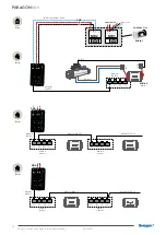
Wiring diagram
Wiring diagram for accessories
24V
G0
G
grey
black
blue (US=black)
brown (US=white)
brown (US=white)
blue (US=black)
|1
2|
3
4|5
6
|7
8|
9
10
11
12
|
|13
14
15
|1
6
17
18
|1
9
20
21
|
| 2 2 | 2 3 | 2 4 | 2 5 |
black
black
white
brown
white
y
24V
brown
blue
black Y-control signal / styrsignal 0-10V DC
Ro
HS
Temperature sensor/
Window contact
Valve actuator,
cooling
Valve actuator,
heating
Key card
Condensation
sensor
CO
2
sensor
24 V AC / DC
Cabel
USB-RJ12
Cable adapter
Pressure sensor
(Modbus)
Adapter
3xRJ12
Adapter
3xRJ12
Motor
Sensor module
VOC-sensor
A
A. Connection when a VOC sensor is used
Inputs
Outputs
ModBus
Motor
Inputs
Outputs
ModBus Motor
Max 48 VA
Max 48 VA
Max 48 VA
The outputs on the regulator
Summary of Contents for PARAGON Wall VAV 1100
Page 6: ...PARAGON VAV 6 Swegon reserves the right to alter specifications 22 11 2021 M8 4 x ...
Page 15: ...15 22 11 2021 Swegon reserves the right to alter specifications PARAGON VAV Maintenance ...
Page 16: ...PARAGON VAV 16 Swegon reserves the right to alter specifications 22 11 2021 Click Click ...


