24
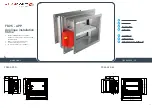
FIRE DAMPER - FD
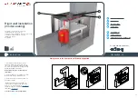
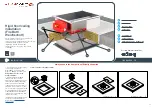
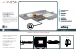
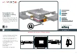
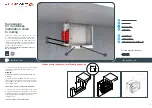
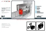
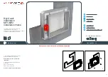
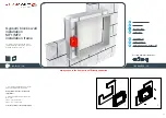
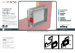
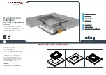
Possible damper orientations
A
C
B
625
625
> 440
625
625
> 440
2
1
3
625
625
> 440
D
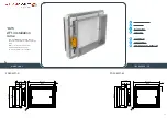
INSTALLATION
E
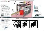
1.
Recommended wall opening for the fire damper
installation is B (H) + 80 mm or more (up to 50% more).
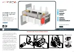
Build the subframe according to the drawing,
46
. Bend the fixing bracket
(A)
90°. Place the damper
in the opening up to the
wall limit mark
(B)
on the
damper.
Damper blade must be closed during the
installation!
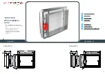
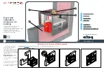
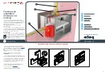
2. Fix the damper to the wall using self-tapping screws
Ø3,5x45 mm (bracket screw hole is 6 mm in diameter).
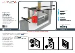
3. Fill the space between the damper and the wall with
mineral wool
(C)
. Cover the mineral wool with GKF
gypsum boards
(12,5 mm thick)
(D)
and fix them with
self-tapping screws Ø3,5x45 mm.
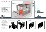
*Multiple fire dampers can be installed next to each
other or ceiling/wall with the minimal distance of
30 mm between them,
.
Test the operation of the damper blade!
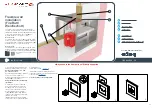
Flexible wall
installation
(mineral wool
sealing)
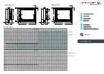
The wall is composed of 2x2 plasterboard boards,
12,5 mm thick, installed on a steel frame construction.
Installation material: mineral wool
(C)
(minimum density
of 100 kg/m³) covered with type F(
EI 120
) or type
A(
EI 60
) cover boards
(D)
.
The minimum thickness of the wall is 100 mm.
EI 90 (ve i
↔
o)S
The wall is made out of type F (EN520) gypsum plaster
boards. To fulfill the classification it is
NOT
mandatory to
use the mineral wool inside the wall (mineral wool
(E)
with
density up to 100 kg/m³ can be used).
EI 60 (ve i
↔
o)S
The wall is made out of type A (EN520) gypsum plaster
boards. To fulfill the classification it is
NOT
mandatory to
use the mineral wool inside the wall
(mineral wool
(E)
with density up to
60 kg/m³ can be used).
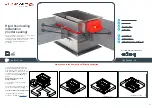
Always e
nsure the damper is sufficiently supported

