background image

SWEISS

WELD.COM

info@sweissweld.com

OPERATION 

16 


TIG short welding 2T


Introduction  


0    

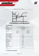
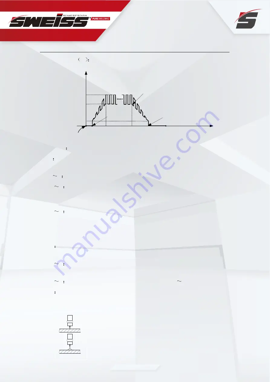
Press  and  hold  the  gun  switch,  Electromagnetic  gas  valve  is  turned  on.  The

shielding gas starts to flow; 


0 t1   Pre flow time, adjustment range of pre flow time :0~1.0S; 


t1 t2  Striking  success,  the  output  current  slopes  up  to  the  setting  current  from 
minimum current (5A); if the output pulse function is turned on, the slope up current is 
pulsed;   


t2 t3  During the whole welding process, the gun switch is pressed and held without 

releasing;   
Note: If the output pulse function is turned on, the output current is pulsed. If the output 
pulse function is turned off, the output current is DC current; 


t3         Loosen  the  gun  switch,  the  output  current  slopes  down;  if  the  output  pulse 
function is turned on, the slope down current is pulsed;   


t3 t4  The output current slopes down to minimum current (5A), stop arc; adjustment 
range of down slope time: 0~5.0S; 


t4 t5  Post flow time, adjustment range of post flow time: 3.0 10.0S;   


t5       Electromagnetic valve is closed and stop argon flowing. Welding is finished. 

The operation step of lifting arc:   


1. Touch the tungsten electrode with workpiece. 

  2. Press the welding gun.   
  3. Lift the welding gun and strike arc. 


Summary of Contents for SKYARC 2030

Page 1: ...info sweissweld com 2009 12 SKYARC 2030 Inverter DC Pulsed TIG MMAArc Welding Machine OPERATOR S MANUAL...

Page 2: ...BLING THE EQUIPMENT TIG 9 4 OPERATION 10 4 1 LAYOUT FOR THE FRONT PANELAND THE REAL PANEL SKYTIG 2030 10 4 2 LAYOUT FOR THE FRONT PANEL 14 4 3WELDING OPERATION 15 4 3 1ARGONARC WELDING OPERATION 15 4...

Page 3: ...ren After shut o the machine power please maintain and examine the equipment according to 5 because of the DC voltage existing in the electrolytic capacitors ELECTRIC SHOCK CAN KILL Never touch electr...

Page 4: ...ctrodes which require special ventilation such as stainless or hard facing or on lead or cadmium plated steel and other metals or coatings which produce highly toxic fumes keep exposure as low as poss...

Page 5: ...ll cracks and openings to adjacent areas Avoid welding near hydraulic lines Have a re extinguisher readily available Where compressed gases are to be used at the job site special precautions should be...

Page 6: ...aps should always be in place and hand tight except when the cylinder is in use or connected for use 1 3 The knowledge of Electric and Magnetic Fields Electric current owing through any conductor caus...

Page 7: ...t protection etc TP series welding machines also have automatic protection functions with intelligent to over voltage less voltage over current and over heat If any one of the above problems happens t...

Page 8: ...ltage by medium transformer the main transformer and rectifying by medium frequency rectifier fast recovery diode and is outputted by inductance filtering The circuit adopts current feedback control t...

Page 9: ...t n e r r u C t u p n I d e t a R Power Factor 0 98 Duty Cycle 40 10 minutes A M M G I T A 0 0 2 0 3 A 0 0 2 0 3 A 0 3 1 0 6 A 0 3 1 0 6 A 0 0 1 0 0 1 A 0 0 1 0 0 1 Max no load Voltage V 71 Welding C...

Page 10: ...output an instruction to cut output welding current and brighten the over heat pilot lamp on the front panel At this time the machine should be relaxed for 10 minutes to cool the fan When operating th...

Page 11: ...efer to packing list in details Those two pipe holder in packing list are used to connect strength pipe with argon gas bottle and shield gas connector The control cable of torch switch consists of 2 w...

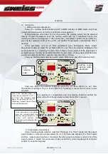
Page 12: ...Crater Current L9 Post Flow Time L10 Pulse Selection light L11 Hot Start L12 Arc Force L13 Alarm Pilot Light L14 Power Pilot Light L15 The function of welding mode selection switch GAS Gas test functi...

Page 13: ...Welding mode selection switch selects MMA mode press the selection knob Step two Adjust the selection knob and select the arc force LED L13 is on Press the selection knob again the arc force LED L13 i...

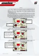
Page 14: ...essing the selection knob or the system will confirm the parameter automatically after 3 seconds Operation flow as follows Step one Welding mode selection switch select TIG 4T or 2T Press the selectio...

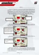
Page 15: ...press the selection knob again the pulse LED L11 is twinkling It means the output pulse function can be turned on or turned off Step three Press the selection knob again the output pulsed conditions t...

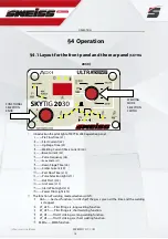
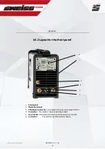
Page 16: ...l 1 Front panel 2 Operation panel 3 Shield gas connector is connected to the gas input pipe of torch 4 Connector the welder s negative polarity output 5 Aero socket is connected to torch switch contro...

Page 17: ...alue adjustment range of up slope time 0 5 0S t3 t4 Welding process During this period the gun switch is loosen Note If the output pulse function is turned on the output current is pulsed If the outpu...

Page 18: ...hout releasing Note If the output pulse function is turned on the output current is pulsed If the output pulse function is turned off the output current is DC current t3 Loosen the gun switch the outp...

Page 19: ...en electrode and prevent tungsten clipping MMA If the electrode touches workpiece over two seconds the welding current will drop to 0 automatically to protect the electrode Automatically purify gas fu...

Page 20: ...xes the electrode swing right and left the electrode moving along welding way The operator can choose the manipulation of electrode based on welding joint sharp welding position electrode spec welding...

Page 21: ...r and electrode diameter Gas nozzle diameter mm Electrode diameter mm 5 0 4 6 0 1 8 4 2 r o 6 1 5 9 2 3 1 1 1 Notice the above parameters originate from Welding Dictionary P142 Volume 1 of Edition 2 W...

Page 22: ...iameter mm welding wire diameter mm Argon gas flow rate L min 1 welding current DCEP Welding speed cm min 1 0 8 Butt joint 1 0 1 6 5 20 50 66 1 0 Butt joint 1 6 1 6 5 50 80 56 1 5 Butt joint 1 6 1 6 7...

Page 23: ...s above the floor level the maximum angle does not exceed 150 Protect the machine against heavy rain or in hot circumstance against direct sunshine Parameters of piping back sealing welding for mild s...

Page 24: ...witch no load voltage may be exported Do not touch the output electrode with any part of your body Before operation no concerned people should be left Do not watch the arc in unprotected eyes Ensure g...

Page 25: ...and switch in the front and at the back of arc welding machine are flexible and put correctly in place If the knob has not been put correctly in place please correct If you can t correct or fix the kn...

Page 26: ...ened or changed Observe that Whether the current output cable is damaged If it is damaged it should be wrapped up insulated or changed Monthly examination Using the dry compressed air to clear the ins...

Page 27: ...onal of our company please contact local our company agent or the branch company If there are some simple troubles of TP series welding machine you can consult the following overhauling chart S N n o...

Page 28: ...is oil or dust on the work piece Check and remove it The distance between tungsten electrode and work piece is too long Reduce the distance about 3mm The distance between the discharger is too short...

Page 29: ...c n e r e f r e t n i r i A Electrode deflection Change new electrode Adjust another angle to weld Magnetic field Use the short arc operation Change the position of earth cable Change welding directi...

Page 30: ...Ddb Drawn By AC 1 AC 3 2 4 R1 R2 C5 24V C3 C4 Tr C16 C17 Pr2 OC1 OC2 Pr1 AC110 220 50 60H Z C14 R13 C15 R14 OUT Lf OUT FAN LED1 LED2 Downslope K2 Pr3 R5 IGBT1 IGBT2 IMOUT MBIN HF QF QD8 QD3 QD1 QD2 I...

Page 31: ...SWEISSWELD COM info sweissweld com NOTES 29...

Reviews: