background image


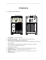
8.


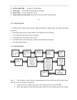
positive output cable       

connected to the work piece


9.


power cable       

connected to the appreciate power supply


10.


power switch   

turn on or off the power source


11.


compressed air connector (Note:

 air pressure has to be set inside. That is 4bar/60psi)


                                                                                            5 

4.2    Cutting Preparation 

1

Tightly connect the power cable to electrical socket outlet (the input voltage, refer to the section 2 technology 

parameters) 

2

connect the air pipe to the air supply equipment, the earth cable to the workpiece 

3

turn on the power switch ,the power source lamp on. 

4

turn the RUN/SET switch to SET position, gas test. 

5

turn the RUN/SET switch to RUN position, regulate the current after the flow stops. 

6

now all the preparation done . 

4.3    Cutting Operation 


Note

:(

1

The alarm lamp on when cutting, it is needed to loose the switch of the torch until the alarm release, 

then press on the switch to start cutting again. 

2

In the automatic gas test and examine, press on the cutting torch, there will no reflection. 

3

After a long usage, the surface of the electrode and nozzle will have Oxidation reaction. Please replace 

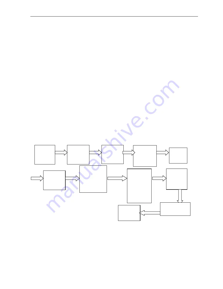
Turn 

on 

the  power 
source 

Automatic 
gas  test  for 
10S 

Loose the 

cutting 

torch 

switch 

Pre-gas 
for 2s 

the torch 

leaves the 

work piece, 

the cutting 
arc change 

into pilot arc 

again 

automatic   
examine for 
5s 

press  on the 
cutting 
switch   
 

Ignite 

the 

pilot arc 

Post-gas  for 

20s 


shift to the 

work piece, the 

pilot arc 

change into 

cutting arc 

Arc 

extinguished 

Summary of Contents for SKYCUT 440

Page 1: ...ely before attempting to use this equipment Save this manual and keep it handy for quick reference Pay particular attention to the safety instructions we have provided for your protection Contact your...

Page 2: ...NPUT POWER CONNECTIONS 4 3 3 GAS CONNECTIONS 4 4 OPERATION 5 4 1 LAYOUT OF THE FRONTAND REAR PANEL TAKE THE CUT 40 FOR EXAMPLE 5 4 2 CUTTING PREPARATION 6 4 3CUTTING OPERATION 6 5MAINTENANCE 7 5 1 BAS...

Page 3: ...tilation is not adequate to remove all fumes and gases The kinds of fumes and gases from the plasma arc depend on the kind of metal being used coatings on the metal and the different processes You mus...

Page 4: ...n area where fire hazards may exist Hydrogen gas may be formed and trapped under aluminum work pieces when they are cut underwater or while using a water table DO NOT cut aluminum alloys underwater or...

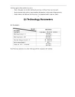
Page 5: ...area from the arc rays Use protective booths screens or shields 2 2 Technology Parameters 2 1Parameters Models Parameters SKYCUT 440 Input power single phase 220V 110V 50 60Hz Rated input current A 23...

Page 6: ...proceeding with the installation 3 2InputPowerConnections Note Check your power source for correct voltage before plugging in or connecting the unit 3 3GasConnections A Connecting Gas Supply to Unit C...

Page 7: ...circuit occurred between the electrode and the nozzle for abnormal reasons the lamp on air feeds intermittently 2 when cutting gun with no electrode and nozzle installed the lamp on air feeds intermi...

Page 8: ...o RUN position regulate the current after the flow stops 6 now all the preparation done 4 3 CuttingOperation Note 1 The alarm lamp on when cutting it is needed to loose the switch of the torch until t...

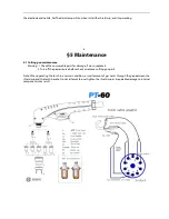
Page 9: ...e consumable parts for damage if worn replace it 2 Turn off the power source before check or remove cutting gun parts Note When operating the torch in a normal condition a small amount of gas vents th...

Page 10: ...er source install and screw it down properly then turn on the power source C The cutting torch fails to ignite the arc when press on the torch switch theTIP GUN GAS lamp on and air feed intermittently...

Page 11: ...at work cable has a proper connection to a clean dry area of the workpiece 3 Faulty components in unit return for repair or have qualified technician repair per Service Manual 4 Faulty Torch return fo...

Page 12: ...4 Faulty components in unit return for repair or have qualified technician repair per Service Manual K No gas flow the power lamp on Fan operates 1 Gas not connected or pressure too low check gas con...

Page 13: ...from clean surface while purging and observe oil or moisture buildup do not activate torch If there are contaminants in the gas additional filtering may be needed 5 3Packinglist 10 Code Name Specific...

Page 14: ...2 MULT 8 CAOUT 5 ISENSE 9 COSZ 18 ROSZ 17 SS 12 VREF 11 LFF 6 SGND 10 PGND 1 VP 3 GDR V 20 VFEED 14 VA OUT 13 VCC 19 IAC 4 VRMS 7 49 81 C 141 R 155 R154 R 1 53 QD6 C 12 1 R178 C 110 R 177 R182 R1 81...

Page 15: ...NOTES...

Reviews: