SWEISS
WELD.COM
info@sweissweld.com
INSTALLATION AND ADJUSTMENT
14
§4 Operation
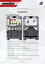
§4.1 Layout for the panel
1
Positive output
The welder’s positive polarity output.
2
Aero socket
Is connected to torch switch control wire.
(
It has 14 leads and lead 8 - lead 9 are
connected to torch switch control wire
)
.
3
Negative output
The welder’s negative polarity output.
4
Shield gas connector
Is connected to the gas input pipe of torch.
5
Power source switch
Switch to “ON”, the welder is turned on, while switch to “OFF”, the
welder is turned off.
6
Power source input
To connect power source.
7
Shield gas input joint
To connect one head of the gas hose while the other head of which is
connected to argon gas cylinder.
8
Fan
It is used for cooling the components and parts inside the welder.
1 220V
ON
OFF
1
2
3
4
5
6
7
8
A
A
V
%
Hz
S
MMA
TIG
TIG
2T
4T
DC
DC
AC
AC
SWEISSWELD.COM
S c h w e i s s t e c h n i k
SKY
TIG
AC/DC
20
30
P

