SWEISS
WELD.COM
info@sweissweld.com
INSTALLATION AND ADJUSTMENT
16
Overview
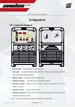
The key feature of the control panel is the logical way in which the controls are arranged. All the main
parameters needed for day-to-day working can easily be
-selected with the keys
-altered with the adjusting dial
-shown on the display during welding.
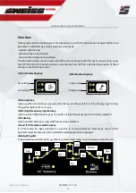
The illustration below shows an overview of the main settings needed for day-to-day working, using
the SKYTIG 2045 ACDC control panel as an example. You will find a detailed description of these
settings in the following section.
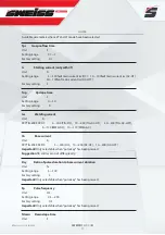
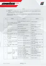
(1) AC/DC selecting key
AC welding
DC welding
(2) Mode selecting key
2-step mode
4-step mode
(3) Gas-test key
Lights up when Gas-test key is pressed, after that gas will flow out for 15s. Press the key again to stop
the gas flow before the 15s are up.
(4) HF (high-frequency) ignition key
Lights up when High frequency key is pressed, HF (high-frequency) ignition has been selected.
(5) Pulse key
Lights up when Pulse key is pressed,
Pulse has been selected.
(6) and (7) Parameter selection keys
If “2T/4T mode” has been selected, it is possible to change parameter indicator by means of the
parameter selection keys (6) and (7) while the welding operation in progress.
(8) Adjusting dial
If the parameter indicator lights up, then the selected parameter can be altered on adjusting dial.
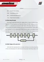
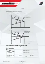
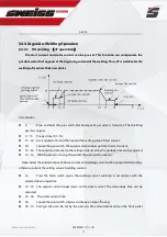
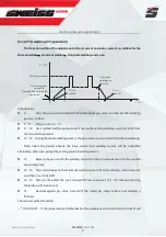
Tpr
Is
Tup
Iw
Ic
Tpo
Tdown
Fp
Dcy
Ib
Iw


