background image

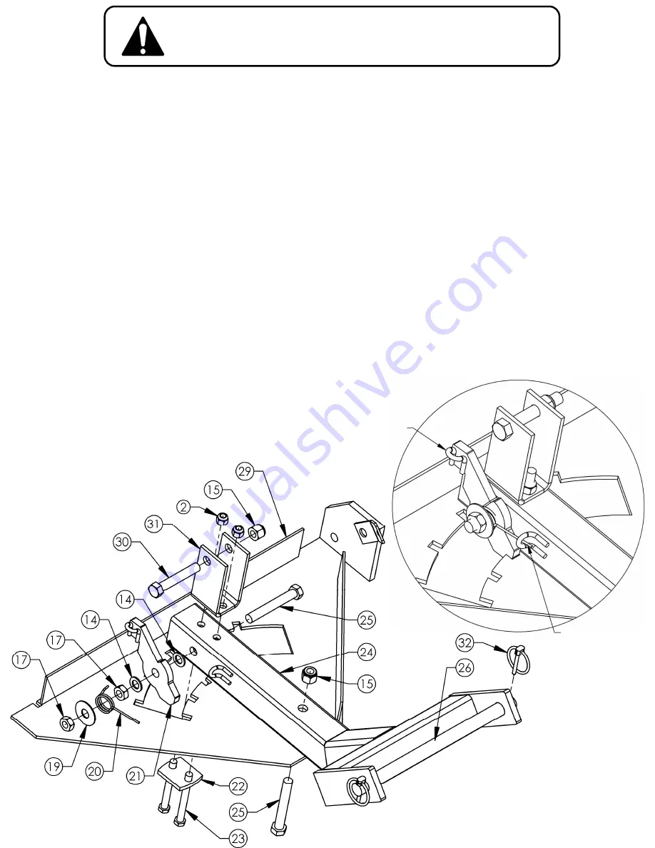
Pivot Latch Assembly

Part of Pivot Weldment 2323
has been hidden for clarity.

5

TO ENSURE PROPER ASSEMBLY, CAREFULLY 

FOLLOW ALL INSTRUCTIONS LISTED BELOW

The numbers in parenthesis 
on this page refer to items 
from the table on page 4.

The tail of Pivot

Spring 2336 must

be inserted into loop.

These steps need to be done in sequence:
1.

Lay parts down in the order they are shown below.

2.

Slide Plow Mount 2588 (24) into Pivot Weldment 2323 (18) and secure with ½-13 X 3½ Bolt 
NB577 (25) and ½-13 Nyloc Nut NB281 (15).  Do not overtighten; the Plow Mount must be 
able to pivot freely.

3.

Assemble the Pivot Latch assembly in the order shown below.  The Pivot Latch assembly 
consists of the following components and is assembled in the following order: ½-13 X 3½
Bolt NB577 (25), Plow Mount 2588 (24), ½ Washer NB177 (14), Lever Latch 2319 (21), ½
Washer NB177 (14), ½-13 Lock Nut NB121 (17), Pivot Spring 2336 (20), 1½ Washer 
TR150W (19), and Lock Nut NB121 (17).  Make sure the tail of the pivot spring is secured 
into the bent metal loop on the Plow Mount.  Do not overtighten; the Lever Latch should be 
able to pivot freely after being assembled.

4.

Attach Plow Support Bracket 2310 (22) and Lift Bracket 2327 (31) to Plow Mount 2588 (24) 
as shown using two NB150 3/8-16 X 3 Bolts (23) and two NB182 3/8-16 Nyloc Nuts (2). 

5.

Insert ½-13 X 3 Bolt NB131 (30) into Lift Bracket 2327 (31) and secure with ½-13 Nyloc Nut 
NB281 (15). Do not overtighten as this can bend the Lift Bracket. This is where you will 
attach your winch or manual lift pulley, sold separately. 

Tie Red Rope H9B (28) to this loop.
Attach Rope Knob H7K (27) to the
other end of the Rope.

Summary of Contents for 2645R ROLLED PLOW BLADE

Page 1: ...PHONE 660 747 8183 FAX 660 747 8650 ade I The USA of US and Global Parts swisherinc com CHANGING YOUR LANDSCAPE SINCE 1945 Starting Serial L212 261001 IMPORTANT Read and follow all Safety Precautions...

Page 2: ...rranty gives you specific legal rights and you may have other rights which vary from state to state This is a limited warranty as defined by the Magnuson Moss Act of 1975 LIMITED WARRANTY The manufact...

Page 3: ...if it has been dropped or damaged in any manner Repair as necessary Dress properly Do not operate when barefoot or wearing open sandals Do not operate the machine while under the influence of alcohol...

Page 4: ...2588 Mount Plow Weldment 9 2317 Edge Cut Reversable 25 X 2 5 X 50 25 NB577 Bolt 1 2 13 X 3 1 2 10 NB127 Pin Hair 39 26 2642 Pin Plow Mount 3 4 X 12 11 NB170 Nut Serrated Flange 5 16 18 27 H7K Knob Ro...

Page 5: ...nents and is assembled in the following order 13 X 3 Bolt NB577 25 Plow Mount 2588 24 Washer NB177 14 Lever Latch 2319 21 Washer NB177 14 13 Lock Nut NB121 17 Pivot Spring 2336 20 1 Washer TR150W 19 a...

Page 6: ...bly to the Blade using 13 X 2 Bolt NB509 13 Washer NB177 14 and 13 Nyloc Nut NB281 15 in the order shown below It is important to ensure the Washer 19 is installed between the Blade and Pivot Mount as...

Page 7: ...2335 9 determine the amount of pressure that must be applied to the Blade before it folds over if an obstruction is hit Tilt Springs 2335 9 can be adjusted by turning 3 8 16 Nyloc Nut NB182 4 on the...

Page 8: ...____________ PART NUMBER WITH PAINT CODE PART DESCRIPTION TELEPHONE 1 800 222 8183 FAX 1 660 747 8650 SWISHER ACQUISITION INC 1602 CORPORATE DRIVE WARRENSBURG MISSOURI 64093 PHONE 660 747 8183 FAX 660...

Reviews: