background image

9

WARNING!

Never start the engine from 

the operating position.

WARNING!

The cutting attachment may 

rotate when the engine is started!

When the Engine Starts...

After the engine starts, allow the 

engine to warm up at idle 2 or 3 min-

utes before operating the unit. 
After the engine is warm, pick  up the 

unit and clip on the shoulder strap.
Advancing the throttle makes the cut-

ting attachment turn faster; releasing 

the throttle permits the attachment to 

stop turning. If the cutting attachment 

continues to rotate when the engine 

returns to idle, carburetor idle speed 

should be adjusted (see "Adjusting 

Engine Idle").


IMPORTANT!

If the engine fails to start after several at-
tempts with the choke in the closed posi-

tion, the engine may be flooded  with fuel. 

If flooding is suspected, move the choke 
lever to open position and repeatedly pull 
the recoil starter to remove the excess 
fuel and start the engine. If the engine still 
fails to start, See the section "Starting a 
Flooded Engine" for instructions.

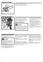
When the engine starts, slowly move the 

choke lever to the "OPEN" position. See 

Figure 10.   (If the engine stops after the 

initial start, close the choke and restart.) 

Figure 10

Open


Primer Bulb

Return Tube

Starting the Engine 

While holding the outer tube firmly with 

your left hand, use your other hand to 

slowly pull the recoil starter handle until 

resistance is felt, then pull quickly to 

start the engine.

Make sure the cutting 

attachment is clear of 

obstructions!

IMPORTANT!

Engine ignition is controlled by a two position switch mounted on the throttle housing labeled, "I" for ON or START and "O" for OFF or STOP.

Figure 6

Figure 7

Figure 9

IMPORTANT! 

The primer system only pushes fuel 
through the carburetor. Repeatedly 

pressing the primer bulb will not flood the 
engine with fuel.

CAUTION! 

Do not pull the recoil starter to the 
end of the rope travel. Pulling the 
recoil starter to the end of the rope 
travel can damage the starter.

ON

Set the throttle lever to the “fast idle”;

Squeeze the throttle lever toward the 

hand grip on the shaft tube.

Depress and hold the throttle lock but-

ton.

While depressing the throttle lock button, 

release the throttle lever. See Figure 6.

Press the primer bulb until fuel can be seen 

flowing in the transparent return tube.

Set the choke lever to the "CLOSED" posi-

tion if engine is cold.

Figure 8

Closed

Throttle Lock  

Button

Ignition Switch

Throttle 

Trigger

Slide the ignition switch to the “ON” posi-

tion. See Figure 6.

WARNING!

Never start the engine with-

out the tool assembly and cutting 
attachments installed to the engine. 
Failure to do so could damage the 
engine and increase unexpected risk 
to the operator and any bystander.

Summary of Contents for E4-S4000

Page 1: ...MANUAL E4 S4000 TRIMMER Part Number 81951 Rev 12 07 Minimize the risk of injury to yourself and others Read this manual and familiarize yourself with the contents Always wear eye and hearing protecti...

Page 2: ...e 15 Troubleshooting Guide 16 Emission System Warranty 18 Contents CAUTION A statement preceded by the word CAUTION contains information that should be acted upon to prevent me chanical damage WARNING...

Page 3: ...gh Wear appropriate footwear non skid boots or shoes do not wear open toed shoes or sandals Never operate the unit while barefoot Keep a proper footing and do not overreach maintain your balance at al...

Page 4: ...or observers outside the 50 foot danger zone wear eye protection Be extremely careful of slippery terrain especially during rainy weather Always make sure the appropriate cutting attachment shield is...

Page 5: ...evel gear EPA Emission Compliance Period Category A The EPA emission compliance referred to on the emission compliance label located on the engine indicates the number of operating hours for which the...

Page 6: ...tra tions that follow Figure 6 3 Turn the cable adjuster in or out as required to obtain proper free play 3 16 1 4 inch 4 6 mm See Figure 8 4 Tighten the locknut Lock Nut 5 Reinstall the air cleaner c...

Page 7: ...It may be necessary to loosen the retaining nut and clamp screw to adjust cutting attach ment shield mounting plate 2 Fit the two shims and the bracket over the outer tube and loosely install the fou...

Page 8: ...is recommended for use in all Swisher low emissions engines and also includes a fuel stabilizer WARNING Minimize the Risk of Fire NEVER smoke or light fires near the engine ALWAYS stop the engine and...

Page 9: ...ing the outer tube firmly with your left hand use your other hand to slowly pull the recoil starter handle until resistance is felt then pull quickly to start the engine Make sure the cutting attachme...

Page 10: ...nnot be serviced in the field E4 S4000 Figure 22 Idle Adjusting Screw NEVER operate the unit with the cut ting attachment shield or other protective devices removed WARNING A cutting attachment shield...

Page 11: ...manually n Flail This device designed for clearing weeds and light brush features three nylon blades attached to the head by pivots NOTE Additional hardware may be required to mount the Fixed Line or...

Page 12: ...ntenance Figure 28A more frequently in dusty conditions 1 Remove the air cleaner cover by loosening the two thumbscrews See Figure 28A 2 Remove and inspect the pre filter If the pre filter is torn or...

Page 13: ...am aged easily 341029 341030 Every 10 to 15 hours of operation Remove and clean the spark plug Adjust the spark plug electrode gap to 0 024 0 028 inch 0 6 0 7 mm If the spark plug must be replaced use...

Page 14: ...may cause hard starting and or can damage the engine n If you are unfamiliar with this engine or uncomfortable with this proce dure consult with an authorized Swisher servicing dealer with limited res...

Page 15: ...e spark plug and pour about 1 4 ounce of 2 cycle mixing oil into the cylinder through the spark plug hole Slowly pull the recoil starter 2 or 3 times so oil will evenly coat the interior of the engine...

Page 16: ...the plug with an NGK CMR5H or equivalent resistor type spark plug of the correct heat range Set spark plug electrode gap to 0 024 0 028 inch 0 6 0 7 mm YES What To Check Possible Cause Remedy Is the...

Page 17: ...g NGK CMR5H or equivalent resistor type spark plug of the correct range Idle engine until cool Cutting attachment rotates at engine idle Engine idle too high Broken clutch spring or worn clutch spring...

Page 18: ...18 NOTES...

Page 19: ...19 NOTES...

Page 20: ...2 Fuel Tank 3 Ignition System Components n Ignition Coil n Flywheel Rotor 4 Catalytic Converter if originally equipped The emission control system for your particular Shindaiwa Corporation engine may...

Reviews: