background image

• Turn off the blades when not cutting.  Before leaving the machine, turn off the blades

and stop the engine.

• Watch for traffic when operating near or crossing roadways.

• Do not operate the cutter if it has been dropped or damaged in any manner or if the 

mower vibrates excessively.  Excessive vibration is an indication of damage.  

Repair cutter as necessary.

• Dress properly.  Do not operate the cutter when barefoot or wearing open sandals. 

Wear only solid shoes with good traction when cutting. 

• Never allow operation by untrained persons.  

• Do not operate the machine while under the influence of alcohol or drugs. 

• Do not operate on slopes greater than 15 degrees.

• Never tamper with safety devices. Check their proper operation regularly.  

• Stop and inspect the equipment if you strike an object.  Repair, if necessary, before

restarting. Never make adjustments or repairs with the engine running.

• Cutter blades are sharp and can cut.  Wrap the blades or wear gloves, and use extra

caution when servicing them. Do not operate at too fast a rate.

• Return lever to its vertical position to disengage blades.

• The braking system is applied when the blades become disengaged. It is designed to

bring the blades to a quick stop (approximately 7 seconds). Each Trailcutter brake

system has been tested and calibrated. For safety, the consumer should not alter the

braking system.

• Disengage spark plug wire and place where it cannot make a connection.

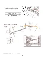
• Refer to Figure 2 p.11.  Attach hitch assembly parts to front of mower .  Insert 3/8-16 X 2 ½ through                     

plate and attach 3/8-16 nut to the bottom.  Tighten nut tight until tube is clamped then back off ½ turn to         

allow tube to pivot.

• The L hitch can be adjusted up or down to level the deck from front to back

• Check engine oil. All engines are filled with oil at the factory. Verify oil level and

add if necessary before starting engine. (See Engine Owner’s Manual)

• Verify fuel level and add if necessary before starting engine.

• Check the battery (if so equipped). If battery is put into service after the “month & year” of the

date on the battery, then it may need to be charged with a 12 volt battery charger for a minimum

of 1 hour, but no more than 2 hours at a rate of 6 to 10 amps.

• Attach battery cable(s) to battery. ( if so equipped ) Red wire to positive (FIRST) and black wire to                      

negative (SECOND).

• Reconnect spark plug wire.

• (Refer to Owner’s Manual p. 5) For proper operating procedures.

ASSEMBLY

4

Summary of Contents for QUADBOSS QBRT14544

Page 1: ...3 FAX 660 747 8650 Manufacturing quality lawn care equipment since 1945 Assembly Operation Service and Adjustment Repair Parts Made In The USA MODEL NO STARTING SERIAL L111 152001 QBRT12544 QBRT14544...

Page 2: ...he fuel system related components which have been certified to this equipment by SAI are to be free of defects in material and workmanship for a period of two 2 years from the date of purchase by the...

Page 3: ...setting up transporting adjusting or making repairs Keep all shields and guards in place Understand the speed steering and stability of this machine Know the positions and operations of all controls...

Page 4: ...system is applied when the blades become disengaged It is designed to bring the blades to a quick stop approximately 7 seconds Each Trailcutter brake system has been tested and calibrated For safety...

Page 5: ...ther approved vehicle It is not recommended for speeds exceeding 5 MPH ATTACHING TRAILCUTTER TO TOW VEHICLE Back vehicle up to desired towing position Offset the Trail Cutter to the side opposite the...

Page 6: ...djustment measure the distance from the bottom edge of the deck in both the front and rear of the deck This adjustment is best done while the tow vehicle and Trailcutter are connected Loosen nuts NB18...

Page 7: ...ble check vehicle to cutter attachment Start mower engine and set throttle to FAST for best cutting performance Slowly engage T handle lever See figure 8 page 16 Carefully mount tow vehicle and start...

Page 8: ...Y MAINTENANCE Make sure all nuts and bolts are tight and cotter pins and retainer springs are secure Keep blades sharp Observe all safety precautions BLADE CARE AND SERVICE For best results cutter bla...

Page 9: ...ectrical connections and inspect spark plug and wire Contact engine manufacturer or qualified mechanic Engine runs poorly See engine manual Check the throttle adjuster Replace fuel clean fuel filter a...

Page 10: ...rt number from Swisher 1 800 222 8183 8 5 CT M F OD82 44 RUGGED CUT DECAL OD29 DANGER DECAL OD39 SWISHER FLAG DECAL OD33 5MPH DECAL OD36 DEFLECTOR DECAL OD55 DANGER DECAL OD45 WARNING DECAL OD10 ENGAG...

Page 11: ...TC TEX RED S SILVER TK TEX BLACK Item Description Part 1 Bolt Serr Flange 1 4 20 X 3 4 GR5 ZY NB690 2 Washer Fender 1 4X1 1 4OD Gr 2 ZY 11520 3 Rubber Flapper 10384 4 Nut Serr Flange 1 4 20 Grade 5 ZY...

Page 12: ...8 UNC X 75 Flange Head NB596 16 Motor Base 10343 17 Cover Rear 17359 18 Nut 5 16 18 Serrated Flange NB170 19 Weldment Axle Bar Left 10355TK 20 1 2 13 Nyloc Nut NB281 21 Spacer 10290 22 5 8 ID X 1 OD 1...

Page 13: ...ated Flange NB170 4 Side Gusset Left 15056 5 Deck Weldment RT44 15727 6 Bracket Remote Cable Detent 15606 7 Weldment Blade Mount 15005 8 Z Bracket Jack Support 15055 9 Remote Cable Mount Bolt On 15059...

Page 14: ...10GA Washer Hardened PLN NB614HT 8 Blade Bearing 4845 9 Tube Spacer 4049 10 Blade Driver 4858TK 11 1 2 13 X 2 HCC GR5 ZP NB509 12 1 2 13 Nylock Nut NB281 13 Spacer BB105SL 14 Blade Pulley 10 3125 4846...

Page 15: ...S 25 3 8 16 X 2 1 2 HTC GR5 ZP NB619 26 3 8 16 HNC GR2 ZP NB212 27 Idler Pulley OD 3 25 ID 3 8 B527 28 3 8 SAE Washer NB272 29 3 8 16 Nyloc Nut NB182 FIGURE 7 BELT ENGAGE CONFIGURATION 1 Engine B S N...

Page 16: ...sher 9088 7 KeySwitchNut 9087 8 KeySwitchON OFF 2 Prong KSM Key Switch 12 VOLT 3623 9 1 4 20 X 2 1 2 HCC GR2 ZP NB141 10 1 4 SAE Washer NB274 11 Console Mount Plate 4852TK 12 1 4 20 Wing Nut ZP NB608...

Page 17: ...WIRING DIAGRAM QBRT11544 QBRT12544 FIGURE 10 17 WIRING DIAGRAM QBRT14544 FIGURE 11...

Page 18: ...olt Wiring Harness Engine 10299 Not Shown Nut 1 4 20 Nyloc NB180 Not Shown Solenoid Assembly 12 Volt 1002004 Not Shown Battery Hold Down 15 Tarp Strap BHOLD Not Shown Battery Cable Black 10 BCS Not Sh...

Page 19: ...onsibilities you should contact the Swisher Service representative at 1 800 222 8183 WARRANTY COMMENCEMENT DATE The warranty period begins on the date the Power Equipment Is purchased LENGTH OF COVERA...

Page 20: ...from the nearest dealer of the engine supplied with your mower WHEN ORDERING PARTS PLEASE HAVE THE FOLLOWING INFORMATION AVAILABLE PRODUCT 44 TRAILCUTTER SERIAL NUMBER _______________ MODEL NUMBER ___...

Reviews: