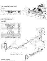
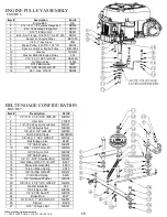
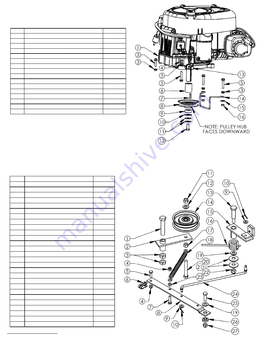
background image

ǧ

15

FIGURE 6

ENGINE PULLEY ASSEMBLY

FIGURE 7

BELT ENGAGE CONFIGURATION

Item #

Description

Part #

1

Engine B&S  

N/A

2

5/16''-18 X 1 1/4'' Serrated Flange Bolt

NB253

3

5/16-18 Serrated Flange Nut

NB170

4

5/16''-18 Nyloc Nut

NB181

5

Bolt - Serr Flange, 5/16-18 X1 3/4 ZY Gr5

NB515

6

Spacer For Engine Pulley

BB105S

7

1/4'' X 1'' Key Stock

9031

8

Engine Pulley- 4.25"OD,1 1/4'' ID

BB105

9

Spacer Lower For Engine Pulley

BB105SL

10

Washer

TR150W

11

Washer Belleville Engine Pulley

699

12

7/16''-20 X 1 HCF GR5 ZP

NB452N

13

Oil Drain Valve

16000

14

RT44 Belt Guide

4867

15

5/16'' USS Flat Washer ZP

NB556

16

Nut - Lock, 5/16-18

NB558

When ordering replacement parts
* = USE PAINT CODE: TC=RED  TK=BLACK
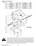
Item #

Description

Part #

1

1/2''-13 X 2 1/2'' HCC GR5 ZP

NB510

2

Idler Arm

21285*

3

1/2''-13 2-Way Jam Lock Nut

NB121

4

1/4''-20 Nylok Nut

NB180

5

1/4''-20 X 3/4'' GR5 ZP

NB250

6

Clutch Cable Clevis

9023MOD

7

1/4''-20 X 1'' HCC GR5 ZP

NB102

8

Belt Engage Arm

4898*

9

1/4'' SAE Washer

NB274

10

5/64'' X 3/4''Cotter Pin

NB519

11

3/8''-16 Nyloc Nut

NB182

12

3/8'' SAE Washer

NB272

13

1/2'' X 1-9/16'' Shoulder Bolt

NB220

14

Idler Pulley OD-3.25", ID-3/8"

B527

15

Brake Arm Assembly

4893

16

Torsion Brake Spring

9040

17

3/8''-16 HNC GR2 ZP

NB212

18

Clutch Rod Spring

682S

19

3/8'' Hardened Washer

NB196

20

3/8''-16 X 2 1/2'' HTC GR5 ZP

NB619

21

Washer Belleville

699

22

3/8-16 Nyloc Nut

NB182

23

1/4''-20 HX Nut ZP

NB139

24

Brake Rod

4891*

25

5/16''-18 X 1'' HCC GR5 ZP

NB501

26

Spacer

B99S

27

5/16''-18 Nyloc Nut

NB181

Summary of Contents for RC11544CL

Page 1: ...bly Operation Service and Adjustment Repair Parts www swisherinc com MODEL NO STARTING SERIAL L118 236001 RC11544CL 21201 REV 18 236 Read and follow all Safety Precautions and Instructions before oper...

Page 2: ...alteration misuse abuse improper assembly or installation shipping damage or to normal wear of the product 4 Exclusions Excluded from this warranty are normal wear normal adjustments and normal mainte...

Page 3: ...n setting up transporting adjusting or making repairs Keep all shields and guards in place Understand the speed steering and stability of this machine Know the positions and operations of all controls...

Page 4: ...ter if it has been dropped or damaged in any manner or if the mower vibrates excessively Excessive vibration is an indication of damage Repair cutter as necessary Dress properly Do not operate the cut...

Page 5: ...uld be towed behind an ATV golf cart lawn tractor or other approved vehicle It is not recommended for speeds exceeding 5 MPH ATTACHING TRAIL CUTTER TO TOW VEHICLE Back vehicle up to desired towing pos...

Page 6: ...stment is best done while the tow vehicle and Trail Cutter are connected Remove hair pins NB127 from clevis pins 18842 so L hitch 18829 can be repositioned Raise or lower hitch section to obtain prope...

Page 7: ...ig 8 pg 16 Carefully mount tow vehicle and start mowing at a slow travel speed STOPPING THE CUTTING SESSION Bring tow vehicle to a complete stop set the parking brake and disengage blades Turn key swi...

Page 8: ...eck blade operation Check for loose fasteners Lubricate threads of adjustment rod P N 4006 See Fig 3 pg 12 DAILY MAINTENANCE Make sure all nuts and bolts are tight and cotter pins and retainer springs...

Page 9: ...onnections and inspect spark plug and wire Contact engine manufacturer or qualified mechanic Engine runs poorly See engine manual Check the throttle adjuster Replace fuel clean fuel filter and fuel li...

Page 10: ...CALS Replace decal immediately if damaged OD29 DANGER DECAL OD33 5MPH DECAL OD36 DEFLECTOR DECAL OD55 DANGER DECAL OD45 WARNING DECAL OD10 ENGAGE DECAL OD99 OFF RUN DECAL 10 OD99112 LARGE SWISHER LOGO...

Page 11: ...7 9 Spacer Straight Hitch 18974 10 Pin Clevis 3 8 X 2 5 18842 11 Arm Hitch Weldment 19132 12 Bracket Hitch Bar Clamp 21147 13 Tube Hitch 18832 14 Pin Clevis 3 8 X 3 75 18843 15 Bolt 3 8 16 X 1 1 4 NB6...

Page 12: ...13 2 Way Jam Lock Nut NB121 15 Weldment Axle Bar Right 10356 FIGURE 3 MOTOR BASE WHEEL HEIGHT ADJUSTMENT ASSEMBLIES 12 Item Description Part 16 Washer Nylon 1 4 NB194 17 Motor Base 10343 18 Cover Rear...

Page 13: ...set Right 15057 6 Z Bracket Jack Support 15055 7 Front Rail Deck Support 15054 8 Remote Cable Mount Bolt On 15059 9 Bracket Remote Cable Detent 15606 10 Rail RT44 Right 17358 11 Weldment Blade Mount 1...

Page 14: ...her 1 X 2 X 14GA NB738 3 Pulley Blade 10 3125 4846 4 Spacer Pulley 21344 5 Bearing Blade 4845 6 Shaft Blade 18844 7 Nut Nyloc 1 2 13 NB281 8 Washer USS Flat 1 2 NB555 9 Blade Driver Housing 4858 10 Bo...

Page 15: ...replacement parts USE PAINT CODE TC RED TK BLACK Item Description Part 1 1 2 13 X 2 1 2 HCC GR5 ZP NB510 2 Idler Arm 21285 3 1 2 13 2 Way Jam Lock Nut NB121 4 1 4 20 Nylok Nut NB180 5 1 4 20 X 3 4 GR...

Page 16: ...eldment 4575 on top of the hitch tube and assemble the console mount plate 4852 from underneath the hitch tube using the hardware provided Make sure the wiring harness is secure and will not drag the...

Page 17: ...17 FIGURE 11 ENGINE TO BLADE PULLEY CONFIGURATION P N B527 P N 4846 P N BB105 P N 20655 WIRING DIAGRAM 11 5HP ENGINE FIGURE 9 PN 19193...

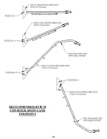
Page 18: ...RECOMMENDED HITCH CONFIGURATIONS AND POSITIONS 18...

Page 19: ...19...

Page 20: ...dealer of the engine supplied with your mower WHEN ORDERING PARTS PLEASE HAVE THE FOLLOWING INFORMATION AVAILABLE PRODUCT RC44 COUNTRY CUT TRAIL CUTTER SERIAL NUMBER _______________ MODEL NUMBER _____...

Reviews: