


딐
Ӈ
•
Disengage spark plug wire and place where it cannot make a connection.
•
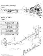
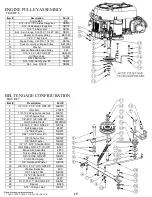
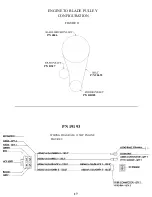
Refer to Fig 2 pg 11. Attach hitch assembly parts to front of mower. Insert 3/8-16 X 2 ½ bolt
through the center hole of the plate and secure with 3/8-16 nut. Tighten nut tight until tube is
clamped then back off ½ turn to allow tube to pivot. Insert 3/8-16 X 2 ½ bolt through one of the
holes that form a circular pattern and secure with 3/8-16 nut.
•
The L hitch can be adjusted up or down to level the deck from front to back
•
Check engine oil. All engines are filled with oil at the factory. Verify oil level and
add if necessary before starting engine. (See Engine Owner’s Manual)
•
Verify fuel level and add if necessary before starting engine.
•
Reconnect spark plug wire.
•
Refer to Owner’s Manual pg 5 for proper operating procedures.
•
Turn off the blades when not cutting. Before leaving the machine, turn off the blades
and stop the engine.
•
Watch for traffic when operating near or crossing roadways.
•
Do not operate the cutter if it has been dropped or damaged in any manner or if the
mower vibrates excessively. Excessive vibration is an indication of damage.
Repair cutter as necessary.
•
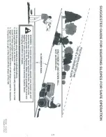
Dress properly. Do not operate the cutter when barefoot or wearing open sandals.
Wear only solid shoes with good traction when cutting.
•
Never allow operation by untrained persons.
•
Do not operate the machine while under the influence of alcohol or drugs.
•
Do not operate on slopes greater than 15 degrees.
•
Never tamper with safety devices. Check their proper operation regularly.
•
Stop and inspect the equipment if you strike an object. Repair, if necessary, before
restarting. Never make adjustments or repairs with the engine running.
•
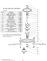
Cutter blades are sharp and can cut. Wrap the blades or wear gloves, and use extra
caution when servicing them. Do not operate at too fast a rate.
•
Return lever to its vertical position to disengage blades.
•
The braking system is applied when the blades become disengaged. It is designed to
bring the blades to a quick stop (approximately 7 seconds). Each Trail Cutter brake
system has been set at the factory. For safety, the consumer should not alter the
braking system.
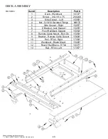
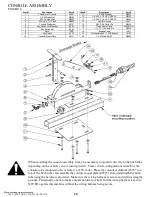
ASSEMBLY
4
ASSEMBLY
ASSEMBLY
Summary of Contents for RC11544CL
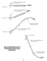
Page 18: ...RECOMMENDED HITCH CONFIGURATIONS AND POSITIONS 18...
Page 19: ...19...


