4
MAINTENANCE
5.
TROUBLE SHOOTING GUIDE
6.
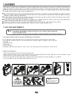
Rinse with clean water externally and internally, to avoid risk of contamination. To keep your sprayer in good condition it is recommended to change the following
parts when servicing your sprayer:
- Checks for O-rings and cylinder - Piston Ring - O-rings Gun - O-ring for pressure chamber - Pump tube o-ring and guide check
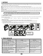
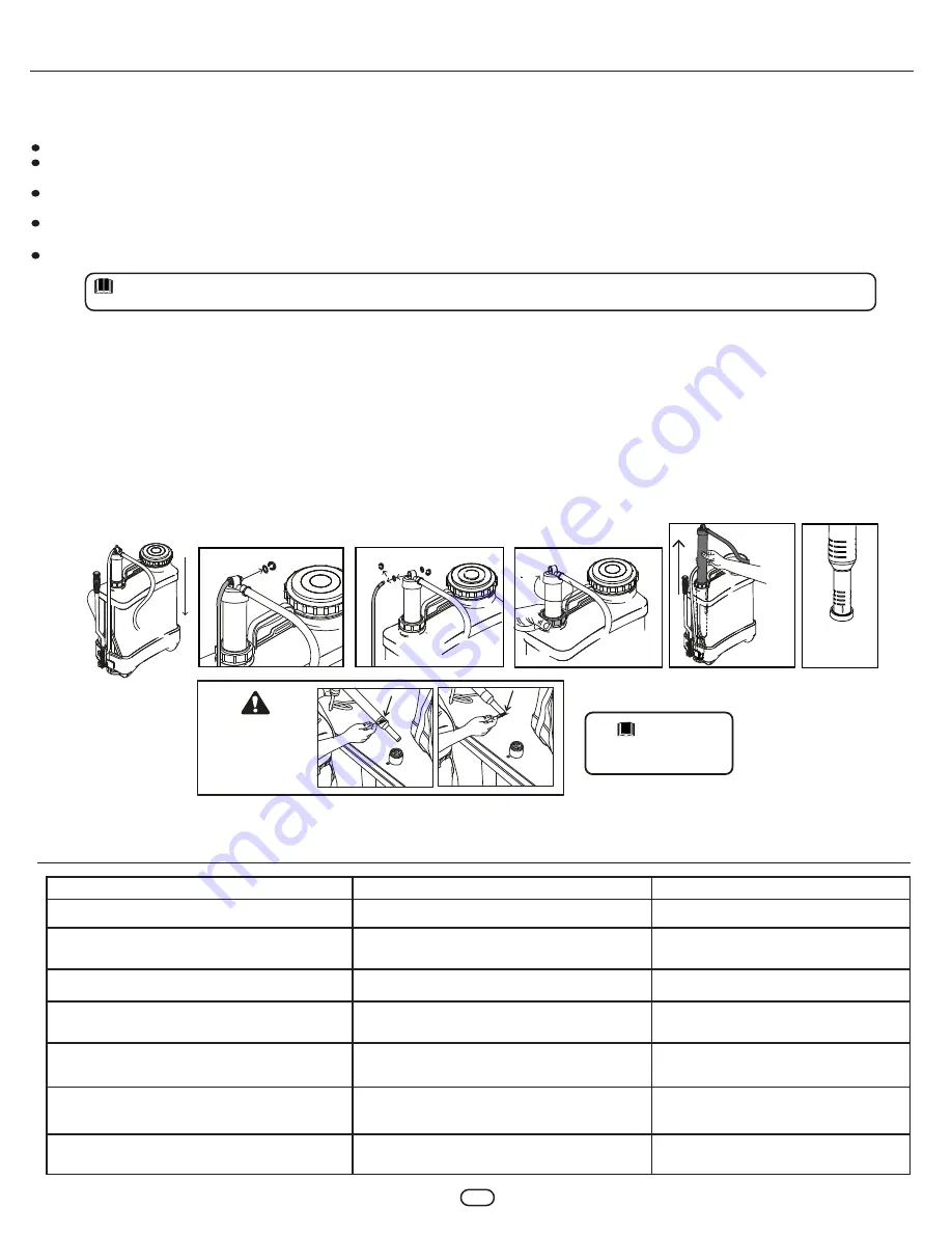
Disassembly instructions:
1.-
Place the sprayer upright on a flat surface. Pull the "R" pin from the upper end of the pump lever. Watch those washers.
2.-
Loosen the pump holder nut atop the tank. Pull out pump tube. To check the ball valve, remove piston fitting and make sure the ball is clean
and in good shape, if not replace it.
3.-
To replace the piston sleeve loose the piston fitting taking care not to lose the check ball; once the piston sleeve has been replaced, tighten
the ball holder nut. Besure the check ball has been set in place. Do not forget to oil it.
Allow pressure to escape. Remove cap and pour out remaining solution, then rinse all parts thoroughly with clean water.
Put approximately ½ gallon of fresh water in the tank, pressurize and flush the pumping system by depressing trigger at least 2 minutes, then drain all remaining
water.
Carrying straps will not absorb chemicals. In the event of a formula spill, however, tank and straps should be properly cleaned with water to eliminate all possible
risk of skin irritation.
A unit that has been used with herbicides should never be used to spray insecticides, unless the sprayer has been properly cleaned and all the chemicals
neutralized. Failure to do this could cause you to kill plants that have been sprayed. Consult the manufacturer of the chemicals in use to obtain proper instructions.
Always store tank clean and empty in a dry, shaded location.
5.1 MAINTENANCE GUIDE
Since the sprayer needs little maintenance, if you follow the steps mentioned in this manual its lifespan will be very long. Do not keep the sprayer with
pressure after finishing your spraying job, release the pressure through the nozzle depressing the trigger, then take the cap and strainer out and pour the
remaining solution. Now rinse system with fresh water as follows:
To keep your sprayer in "optimal" conditions of use is necessary to maintain oiled
"Always" the following parts: The o-rings gun, piston ring, breathing valve cover gasket,
- Pump tube gasket and guide check.
NOTE:
ATTENTION
OIL PUMP TUBE AND
PISTON SLEEVE
BEFORE ASSEMBLING
IN THE SPRAYER
To lubricate all parts; Use
silicone-based grease.
NOTE:
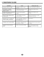
PROBLEM
The tank collapses when pressuring it.
CAUSE
SOLUTION
The breather check needs lubrication.
Lubricate or replace if damaged.
The piston sleeve does not run smoothly
and it is hard to pump.
The piston sleeve is stuck.
Replace the piston sleeve and lubricate.
The piston sleeve does not keep pressure.
The piston sleeve is worn out or shrunk.
Replace the piston sleeve and lubricate.
The sprayer does not build pressure.
The ball valve is stuck or dirt is preventing the
ball valve to sit properly on the ball-holder nut.
Clean the ball holder nut, and the ball
valve, replace them if necessary.
When pumping a creak is produced between
the pump tube and pump holder nut.
The pump tube and pump holder
nut need lubrication.
Lubricate both of them.
The shut-off valve does not close after
releasing the trigger.
The plunger o-rings are worn out
or swollen.
Replace them and lunricate the plunger
with the new O-rings.
The shut-off valve does not function
when pushing the trigger.
Filter or nozzle are blocked.
Clean the nozzle.

