_____________________________________________________________________________________
SWS – 7695 Blackburn Parkway, Niagara Falls, ON Canada
Tel: 1-877-357-0222 | Fax: 905-357-9122 | sales@swssafety.com
300197 Rev. 2
Page
2
of
5
Mounting
Permanent Mount
Select a surface where the light is visible and free of obstruction. Mounting brackets are available from the
manufacturer.
1.
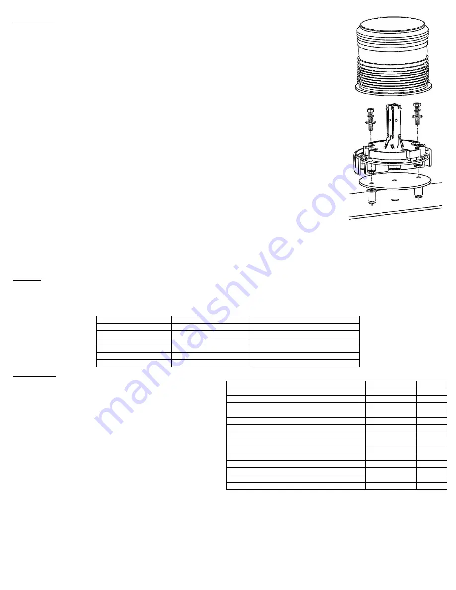
Using
a 3/8” drill bit and the foam gasket pad as a template, drill two holes into the mounting surface, 2-3/4” apart. Be
sure to drill a hole in the center for the wires.
2.
Place two rubber expansion nuts into the
3
/
8
” holes in the mounting surface.
3.
Remove lens from base by removing the screw in the banding ring or gently prying the plastic lens tabs with a flat
screwdriver. Lift banding ring (if present) and lens away from base.
4.
Locate the two mounting bosses on the base, designated by two recesses in the base, and drill them out with a
7
/
32
”
drill bit.
5.
Place an external tooth lock washer and a flat washer on each screw, and insert the screws into the pre-drilled holes
of the light, from the inside of the light.
6.
Place the foam pad on the mounting surface, aligning the holes with the expansion nuts. Place the light on the pad,
passing the wires through the center hole, and tighten screws. Reassemble the lens and banding ring (if present).
½” NPT Conduit/Pipe Mount
1.
Thread wires through pipe/conduit. This may have to be done after wiring to ensure proper length of the wires.
2.
Thread light no more than
3
/
8
” onto the pipe/conduit using the center ½” NPT hole in the base.
3.
Secure the light tightly to ensure proper connection to the pipe/conduit. Be careful not to over-tighten. Thread tape
or a locking nut can be used but is not supplied.
Magnetic Mount & Operation
1.
Apply the supplied vinyl magnet cover to the bottom of the magnet.
2.
Remove any debris (dirt, film, water, etc.) from the magnet and the mounting surface before placing the light on the
surface.
3.
Once product is in place, route cigarette cord into the vehicle through the window,
Not the Door.
4.
Ensure the cable
is not interfering with the driver’s visibility, the operation of the steering wheel, or other important
controls.
5.
Plug cord into cigarette lighter and use switch to turn ON (red LED will light up).
6.
The secondary switch (where present) can be used to cycle through the available patterns.
7.
To remove the light, pull the light
by the base
.
Mirror Bracket Mount
A Mirror Mount Bracket kit (kit #175) is required for this mounting option.
Follow the instructions that come with the mirror mounting kit.
Wiring
All extension wires need to be appropriately sized depending upon the length that they are to travel. SWS recommends a minimum of 20AWG and that
for every additional 10ft. of length, the gauge be increased (i.e. for a length of 11ft, the minimum gauge for power wires would be 18AWG).
If you are unsure of your wire gauge or want to use a lesser gauge, check the voltage at the product wire connection to ensure the light will receive
adequate power.
Wire Colour
Product Wire Gauge
Wire Function
Red
18-20 AWG
Positive (+)
Black
18-20 AWG
Negative/Ground (-)
Green
22 AWG
Pattern Select (Where applicable)
Violet
22 AWG
AutoDim/Manual Dim Enable
Blue
22 AWG
Master/Slave Select
White
22 AWG
LIN Communication
Operation
Pattern Selection
If you wish to have only one (1) pattern, select the pattern by
momentarily touching the GREEN wire to the BLACK (Ground).
After the desired pattern is selected, secure the GREEN wire away
with a wire nut, or tape the end to ensure no further pattern change.
If you have a model with the GREEN wire connected to a
momentary switch, the different patterns can be cycled through
(switch kit #766163).
2071x, 2072x, 2073x, & 2074x series lights do not have pattern
select, and will operate at 1Hz single flash. If you desire a faster
2Hz single flash pattern, cut the resistor that is protruding from the
circuit.
AutoDim and Manual Dim (2079x Models Only)
Magnetic Mount lights
do not
have the ability to dim.
The VIOLET wire allows for dimming. If you are not using the
dimming feature, isolate and stow away the violet wire.
To engage the AutoDim function, permanently connect the VIOLET wire to GROUND. This will engage the internal photosensor, and the light will
automatically dim based upon the ambient lighting intensity level.
To manually dim the light, connect the VIOLET wire to POSITIVE. This should be done via an external switch.
Flash Pattern
Frequency
FPM
Single Flash
1.33
61
Double Flash
1.33
159
Triple Flash
1.07
193
Quad Flash
1.13
272
Quint Flash
1.03
310
Fast Flicker
1.41
677
Double Flash Illusion Gen2
N/A
N/A
Flicker Flash with Night Indicator
N/A
N/A
CCW Rotating Fast
2
120
CCW Rotating Slow
1
60
CW Rotating Fast
2
120
CW Rotating Slow
1
60
Marine Steady Burn
N/A
N/A
Marine SOS
N/A
N/A


