background image

Page

11.  Wiegand function ........................................................................................................ 52

a) Connection .......................................................................................................... 52
b)  Setting Wiegand device ID .................................................................................. 53

c)  Configuring the Wiegand output

 .......................................................................... 54

d)  Using fingerprints with the Wiegand controller

 .................................................... 55

12.  Interlock function ........................................................................................................ 56
13. Operation .................................................................................................................... 57

a)  Enabling the changeover contact ........................................................................ 57
b)  Enabling the changeover contact via button ....................................................... 57
c)  Terminating the alarm sound ............................................................................... 57
d)  Superuser lock function ....................................................................................... 58

14.  Sound signals and LED displays ................................................................................ 59
15. Troubleshooting .......................................................................................................... 60
16.  Care and Cleaning ..................................................................................................... 61
17.  Declaration of Conformity (DOC)................................................................................ 61
18. Disposal ...................................................................................................................... 62

a) Product ................................................................................................................ 62
b)  Battery information .............................................................................................. 62

19.  Technical Data ............................................................................................................ 63

a)  Code lock ............................................................................................................ 63
b)  IR remote control ................................................................................................. 63

3

Summary of Contents for 1888207

Page 1: ...Operating Instructions Fingerprint code lock Item No 1888207...

Page 2: ...notes 23 b Activating exiting programming mode 24 c Changing the master code 25 d Setting the user fingerprint 26 e Tuning in the user transponder 30 f Deleting the user ID 37 g Deleting the user fing...

Page 3: ...peration 57 a Enabling the changeover contact 57 b Enabling the changeover contact via button 57 c Terminating the alarm sound 57 d Superuser lock function 58 14 Sound signals and LED displays 59 15 T...

Page 4: ...in this manual These operating instructions are part of this product They contain important infor mation on setting up and using the product Do not give this product to a third party without the oper...

Page 5: ...d fingerprint sensor If you hold a tuned in transponder in front of the code lock or place a finger that is stored in the system on the fingerprint sensor a potential free changeover contact will be a...

Page 6: ...1x transponder card for deleting user transponders Mounting material 2x screws 2x dowels 1x L key 3x 1N4004 diodes Operating instructions Up to Date Operating Instructions Download the up to date ope...

Page 7: ...r the potential free changeover contact specified in chapter Technical data Never attempt to connect the code lock to a mains voltage as this may cause a fatal electric shock Please handle the product...

Page 8: ...r children Maintenance modifications and repairs must be carried out by a technician or a specialist repair centre If you are not sure how to operate the product correctly or if you have any questions...

Page 9: ...Never attempt to recharge non rechargeable batteries as this may cause an explosion Old or depleted batteries may emit chemical liquids that cause damage to the product Therefore if the device is not...

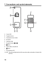
Page 10: ...nt sensor C Transponder sensor surface D IR receiver E Fastening screw F Keypad for buttons to G button H Clip for battery compartment I button J IR transmission LED The wall mounting bracket and the...

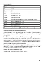
Page 11: ...ires power for the alarm output siren up to 2 A Potential free changeover contact cable blue purple orange The potential free changeover contact for contact rating see Technical data chapter is ac tiv...

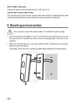
Page 12: ...nt 8 Mounting and connection Do not mount or connect the product when it is connected to a power supply Unscrew the screw see chapter 7 item E on the bottom of the code lock an L key for the special s...

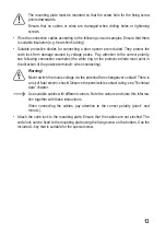
Page 13: ...hite ring on the protective diode must point in the direction of the positive terminal when connecting Warning Never switch the mains voltage via the potential free changeover contact There is a risk...

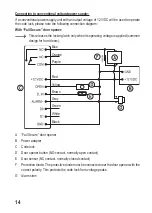
Page 14: ...h only when its operating voltage is applied common design for front doors Blue Orange Purple Red Yellow Brown Grey Green White Black A Fail Secure door opener B Power adapter C Code lock D Door opene...

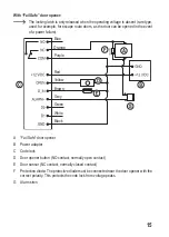
Page 15: ...wer failure Blue Orange Purple Red Yellow Brown Grey Green White Black A Fail Safe door opener B Power adapter C Code lock D Door opener button NO contact normally open contact E Door sensor NC contac...

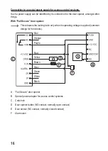
Page 16: ...r opener This releases the locking latch only when its operating voltage is applied common design for front doors Blue Orange Purple Red Yellow Brown Grey Green White Black A Fail Secure door opener B...

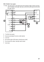
Page 17: ...route doors as the door can be opened in the event of a power failure Blue Orange Purple Red Yellow Brown Grey Green White Black A Fail Safe door opener B Special power adapter for access control sys...

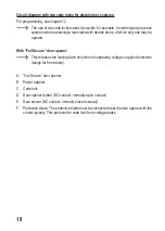
Page 18: ...pened With Fail Secure door opener This releases the locking latch only when its operating voltage is applied common design for front doors A Fail Secure door opener B Power adapter C Code lock D Door...

Page 19: ...Blue Orange Purple Red Yellow Brown Grey Green White Black Blue Orange Purple Red Yellow Brown Grey Green White Black 19...

Page 20: ...be opened in the event of a power failure A Fail Safe door opener B Power adapter C Code lock D Door opener button NO contact normally open contact E Door sensor NC contact normally closed contact F P...

Page 21: ...Blue Orange Purple Red Yellow Brown Grey Green White Black Blue Orange Purple Red Yellow Brown Grey Green White Black 21...

Page 22: ...ctly ori ented battery holder back into the IR remote control the plus pole of the battery should point towards the bottom of the IR remote control A battery change is required if the IR range has dec...

Page 23: ...hat you also assign a user ID for each fingerprint and transponder that you want to tune in to the code lock You should enter it together with other data employee name fingerprint or tran sponder acce...

Page 24: ...e code lock has detected the IR signal of the remote control the control LED on the code lock flashes red the code lock will automatically return to standby mode after four seconds without any further...

Page 25: ...r example The master code must always consist of six digits Press the button to confirm your entry The control LED will light up green briefly for confirmation then it will light up orange Enter the n...

Page 26: ...determine which one has been assigned If you do not assign a specific user ID to a user and enter it in a list this can lead to problems later Because if an employee leaves the company or loses a user...

Page 27: ...inger on the fingerprint sensor again When the fingerprint has been detected and matches the first one the code lock emits a beep and the control LED lights up green briefly The control LED will then...

Page 28: ...finger on the fingerprint sensor again When the fingerprint has been detected and matches the first one the code lock emits a beep and the control LED lights up green briefly The control LED will then...

Page 29: ...again When the fingerprint has been detected and matches the first one the code lock emits a beep and the control LED lights up green briefly The control LED will then light up orange again The new u...

Page 30: ...ards which one has been assigned If you do not assign a specific user ID to a user and enter it in a list this can lead to problems later Because if an employee leaves the company or loses a user tran...

Page 31: ...the code lock below the fingerprint sensor When the transponder has been detected the code lock emits a beep and the control LED lights up green briefly The control LED will then light up orange agai...

Page 32: ...t in front of the code lock below the fingerprint sensor When the transponder has been detected the code lock emits a beep and the control LED lights up green briefly The control LED will then light u...

Page 33: ...now in tuning in mode To tune in a user transponder just hold it in front of the code lock below the fingerprint sensor When the transponder has been detected the code lock emits a beep and the contro...

Page 34: ...fly and then orange again Enter the 8 or 10 digit transponder number Press the button to confirm The control LED will light up green briefly and then orange again The new user transponder is stored in...

Page 35: ...code lock is now in tuning in mode Enter the 8 or 10 digit transponder number Press the button to confirm The control LED will light up green briefly and then orange again The new user transponder is...

Page 36: ...g in mode Enter a start user ID a number of The transponders are stored from this user ID Make sure that there is enough free memory for the transponders after the start user ID otherwise the code loc...

Page 37: ...ised person see chapters 10 d and 10 e If you want to delete a user ID with a user fingerprint or user transponder stored in it proceed as follows The code lock must be in standby mode the control LED...

Page 38: ...When the fingerprint has been detected the code lock will emit a beep and the control LED will briefly light up green The control LED will then light up orange again The user fingerprint has been del...

Page 39: ...m the code lock system on the fingerprint sensor When the fingerprint has been detected the code lock will emit a beep and the control LED will briefly light up green The control LED will then light u...

Page 40: ...elow the fingerprint sensor When the transponder has been detected the code lock emits a beep and the control LED lights up green briefly The control LED will then light up orange again The user trans...

Page 41: ...der just hold it in front of the code lock below the fingerprint sensor When the transponder has been detected the code lock emits a beep and the control LED lights up green briefly The control LED wi...

Page 42: ...ht up green briefly and then orange again The user transponder is deleted If the card number cannot be found in the code lock memory the code lock emits three short beeps the control LED flashes red a...

Page 43: ...hen the control LED will flash red Example Press the button The control LED will light up orange The code lock is now in delete mode Enter the master code for example Press the button to confirm your...

Page 44: ...ch valid access attempt optimal e g for activation deactivation of an alarm system Proceed as follows The code lock must be in standby mode the control LED lights up red Activate programming mode as d...

Page 45: ...der in front of the sensor surface or place your finger on the fingerprint sensor If the transponder or the fingerprint is valid the changeover contact will be acti vated Activating the changeover con...

Page 46: ...ly via the transponder Access via the transponder or fingerprint by default Access only via the fingerprint Access via multiple different transponders fingerprints Directly after selecting function en...

Page 47: ...stable 1 3 minutes Proceed as follows The code lock must be in standby mode the control LED lights up red Activate programming mode as described in chapter 10 b then the control LED will flash red Exa...

Page 48: ...and the alarm output will be activated thus an alarm siren can be operated otherwise the alarm output can be connected to an alarm system The alarm duration is adjustable 1 3 minutes is possible one...

Page 49: ...te of a valid access attempt using a transponder or fingerprint the code lock will emit an alarm sound and the alarm output will be activated An alarm siren can be connected to the alarm output otherw...

Page 50: ...ion Master Add Card This card can be used to tune in new transponders Inscription Master Delete Card This card can be used to delete tuned in transponders When the code lock is reset the data of these...

Page 51: ...ransponder is the one with which tuned in transponders can be deleted Master Delete Card After the second transponder has been tuned in the control LED lights up green briefly and then glows red stead...

Page 52: ...as an external reader connected to a Wiegand controller Follow the operating instructions for the controller or monitoring system operating the code lock a Connection Red Green White Black A Code loc...

Page 53: ...user ID of the valid fin gerprint is 3 the virtual transponder number 255 00003 will be transmitted example for Wiegand controllers with a bit rate of 26 bits Proceed as follows The code lock must be...

Page 54: ...ED lights up red Activate programming mode as described in chapter 10 b then the control LED will flash red Example Press the button The control LED will light up orange Now either disable the Wiegand...

Page 55: ...ed in chapter 10 d If necessary set an unused device ID for the code lock as described in chapter 11 a To tune in new transponders via the Wiegand interface switch the Wiegand controller or the Wiegan...

Page 56: ...en the control LED will flash red Example Press the button The control LED will light up orange Enter the desired function Interlock function disabled default setting Interlock function enabled Press...

Page 57: ...apter 8 the changeover contact can be activated by briefly pressing the button The activation time is the same as that used for a valid user transponder or user fingerprint the button can be used in t...

Page 58: ...der stored in the aforementioned user IDs The control LED will flash red several times The code lock will emit a long beep and the control LED will glow red steadily The code lock is now locked In thi...

Page 59: ...1x short beep Error LED flashes red three times 3x short beep Valid access attempt via transponder or fingerprint LED flashes green once 1x long beep Door opener button is pressed LED flashes green on...

Page 60: ...print or transponder is not tuned in The changeover contact cannot be activated with the superuser fingerprint or superuser transponder The transponder does not work Always hold only one transponder i...

Page 61: ...se aggressive detergents rubbing alcohol or other chemical solutions as these may damage the case or cause the product to malfunction 17 Declaration of Conformity DOC Conrad Electronic SE Klaus Conrad...

Page 62: ...all used batteries rechargeable batteries Disposing of them in the household waste is prohibited Contaminated rechargeable batteries are labelled with this symbol to indicate that disposal in the dome...

Page 63: ...t Potential free single pole changeover contact relay Contact rating max 12 24 V DC 1 2 A Switching time adjustable 100 ms or 2 99 seconds or toggle operation Alarm output yes 12 V DC max 2 A Memory T...

Page 64: ...ncluding translation reserved Reproduction by any method e g photo copy microfilming or the capture in electronic data processing systems require the prior written approval by the editor Reprinting al...

Reviews: