


10
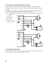
b) Connecting to conventional voltage/power supply
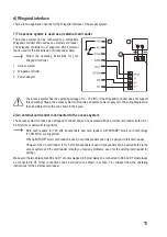
When a conventional power supply unit should be used, observe the following figures with the wiring diagram.
A) “Fail-secure” door opener: Releases the locking latch only when its operating voltage is applied (common design
for front doors).
B) “Fail-safe” door opener: releases the locking latch only when the operating voltage is missing (uncommon design,
e.g. used for escape route doors, which can be opened in the event of a power outage).
The included diode must be connected correctly near the door opener to protect the access system from
voltage surges.
1 Access system
2 Door opener button
3 Power adapter
4 “Fail-Secure” door opener
5 “Fail-Safe” door opener
c) Connecting to alarm system
Observe the operating instructions for the alarm system used. The access system relay switches when a valid tran-
sponder is recognised. The alarm system can thus be enabled or disabled.
1
2
3
4
5
1
2
3
Summary of Contents for 2380477
Page 1: ...Operating Instructions RFID access system Item no 2380477 ...
Page 29: ...29 ...
Page 30: ...30 ...
Page 31: ...31 ...


