•
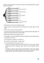
Brown cable: Connection for door contact (e.g. magnetic/reed switch)
If the door contact is not assigned, connect the brown cable to the negative pole (GND/-) of
the power supply (black cable). If the door contact is interrupted, the operation is disabled and
the LED flashes green and blue alternately.
•
Orange/purple cable: AUX output, NO/normally open contact; various functions can be
selected, see section 8. p)
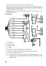
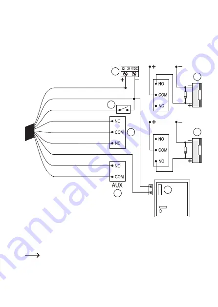
Wiring example:
1 Power adapter
2 Door opener button
3 Changeover contact
4 AUX output
5 “Fail-secure” door opener (common design for entrance doors)
6 “Fail-safe” door opener (uncommon design, e.g. used for escape route doors)
7 Door contact (e.g. magnetic/reed switch)
If the door opener has no built-in protective diode against voltage surges, it must be
connected with the correct polarity next to the door opener (not included, e.g. type
1N4004 or similar).
1
2
3
4
5
6
7
Red
Black
Green
White
Yellow
Blue
Brown
Orange
Purple
48

