9. Operation
a) Getting started
Power on the code lock once it has been connected and installed. After powering on the code
lock, the LED lights up yellow briefly and then glows blue steadily with two beeps.
The code lock is now ready for use and can be programmed.
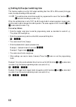
If the LED flashes green and blue alternately, the door contact (brown cable, “reed”) is
interrupted.
The code lock cannot be programmed in this case.
Close the door so that the door contact is not interrupted. The brown cable (“reed”)
can also be connected to GND/- (black cable). Doing so simulates a closed door.
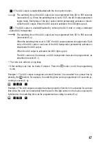
If button operation is disabled (e.g. programming mode cannot be started using the
master code, as described in section 8. a), the light sensor on the back of the code
lock is exposed to light beams.
You should take the following steps:
• Create a table and fill in all settings, user/transponder numbers and codes.
•
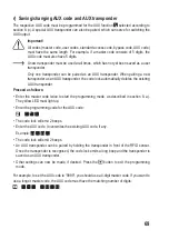
Think of a master code (consisting of 4 to 8 digits) and programme it (see section 8. b).
Make sure all codes (master code, user codes, standard access code, bypass code,
AUX code) have the same length.
If, for example, you want to use a 5-digit master code instead of the 4-digit one, you
should first reset the code lock to factory defaults (section 8. t) and then clear all user
memory cells (section 8. g).
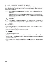
Though the transponders would still work after setting a new master code with a dif-
ferent number of digits, the stored 4-digit user codes will be rendered invalid.
• Save a new transponder as a master transponder (see section 8. s). It simplifies the pro
-
gramming process since you should only hold it once in front of the RFID sensor to start the
programming mode, and you do not need to enter the master code twice.
•
Select the access mode (see section 8. c).
•
Pair the user transponder with the code lock (see section 8. e).
•
You will now need to assign a separate user code for each user transponder (see section 8.
f) or set a standard access code (see section 8. d) according to the selected access mode.
73

