


10
COMMISSIONING AND MAINTENANCE
b
If copper piping has been used and joints have been
hot brazed, flush out the system to remove any braz-
ing residues. Seal test the system after you have
flushed it out.
b
The solar circuit must be immediately filled with a
mixture of water and glycol, that avoids freezing and
corrosion.
15 SYSTEM FILLING COCK
Before filling the system:
- Cut power off to the solar station and to the connect-
ed integration system, by setting the system's main
switch and the device's main switch to OFF
b
Always use a mixture of water and glycol suitable for
solar applications. Choose the mixture according to
the minimum temperature that can be reached at the
installation site and to the maximum service tempera-
ture of solar collectors. For further information, please
refer to the glycol safety data sheet.
When using glycol not pre-mixed:
- Do NOT part fill the circuit with pure glycol then add
water later.
- Ensure that filling water characteristics comply with
prevailing regulations; if that is not so, filling water
must be treated. Use portable treatment systems, for
instance. In particular, when chlorine content is very
high (> 50ppm) you must use distilled water for the
mixture.
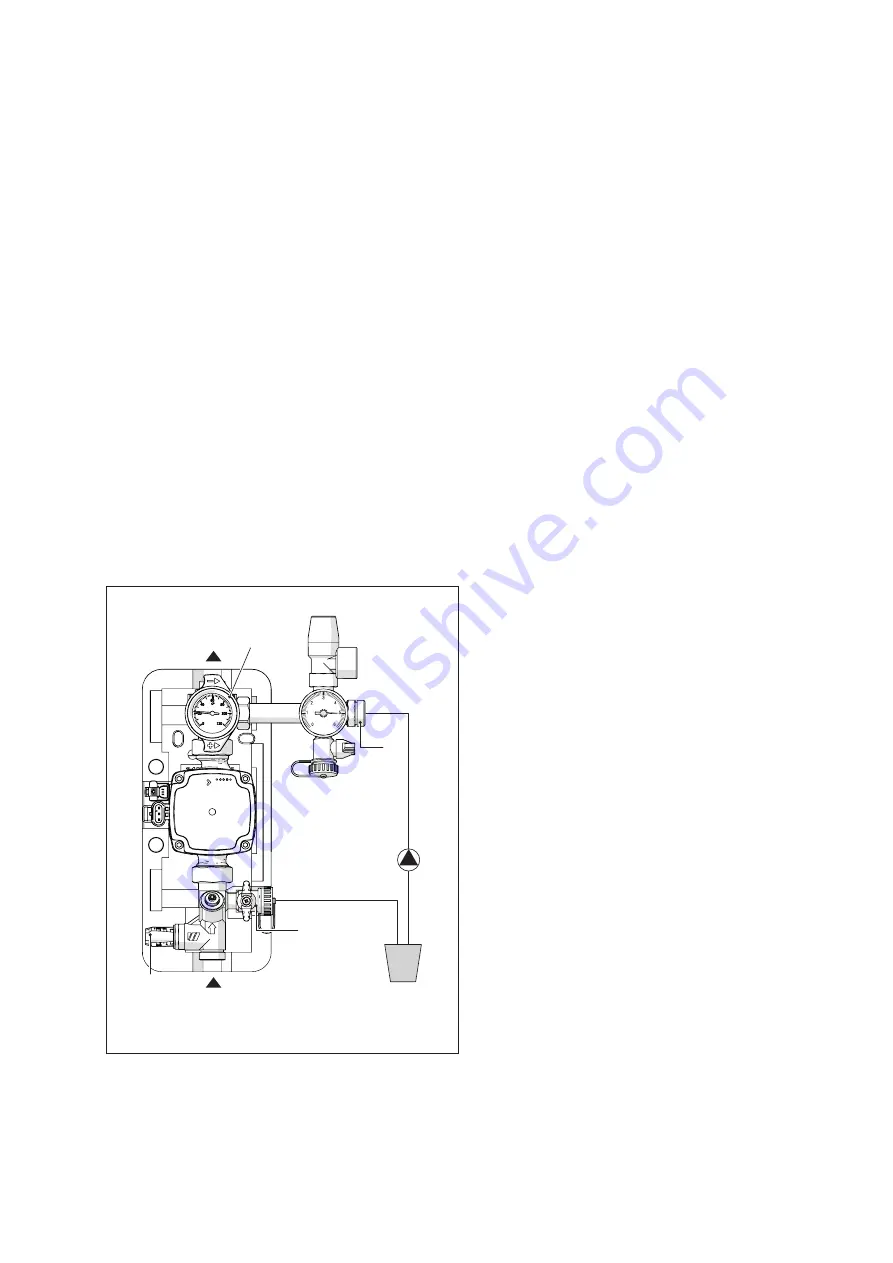
VR
B
A
C
Mixture
of glycol
and water
PC
PC
Heat transfer fluid filling pump
To fill the system, proceed as follows:
- Verify the flow-meter (C) is completely open
- Connect the filling pump (PC) as shown
- Turn handle on valve (VR) clockwise
Open taps (A) and (B) on the return tube
- Open manual degassing tap and any bleeder valve,
located at the highest points of the system, and keep
them open throughout the filling procedure.
- Pump the heat transfer fluid around the circuit with an
external filling pump until all air bubbles have been
eliminated. Close the manual bleed valve and any
vent valves opened previously.
- Turn handle on valve (VR) counter clockwise
- Temporarily raise the pressure in the system to 4 bar.
- Start up the system for about 20 minutes.
- Repeat air bleeding operation until system is com-
pletely free of air bubbles.
- set the system pressure.
- Close taps (A) and (B).
b
The set pressure must ensure that the one measured
at the solar collectors is positive with respect to the
ambient one (avoid depression in the solar field) and
must be set considering both the safety valve open-
ing pressure (6) and the solar expansion reservoir
pre-charge pressure. To set the system pressure cor-
rectly, refer to the design manual.
a
Do not fill the system in bright, sunny conditions or if
the collectors are hot.
b
Use a manual bleed valve, which should be installed
at the highest point in the system, to ensure that all air
bubbles have been eliminated from the circuit.


