


4
GENERAL INFORMATION
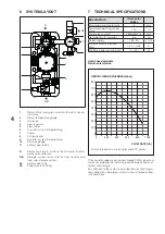
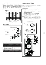
6 SYSTEM LAYOUT
12
3 4
5
0 6
R
RB
7
8
6
SV
VE
10
9
11
1
2
4
5
3
1
Return Valve (solar plant return) with built-in non-re-
turn valve
2
Return temperature gauge
3
Insulation
4
Flow regulator
5
Flow-meter
6
Tap A for system filling/draining
7
Pump
8
Fixing bracket
9
Tap B for system filling/draining
10
Pressure gauge
11
Safety valve (6 bar)
R
Solar circuit return. Outlet of heat transfer fluid to-
wards solar collector.
RB
Storage system return. Inlet of heat transfer fluid
from solar storage system.
SV
Safety valve drain
VE
Expansion tank fitting
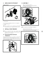
7 TECHNICAL SPECIFICATIONS
DESCRIPTION
return solar
station
Maximum working pressure
6
bar
Maximum operating temper-
ature
110
°C
Dimensions LxHxP
264x362x215
mm
Net weight with insulation
3,8
kg
Power supply
230~50
V~Hz
Min/max electrical current
draw
0,04 ÷ 0,48
A
Min/Max power consumption
2 ÷ 45
W
Useful head available
Return solar station
USEFUL HEAD AVAILABLE (mbar)
800
700
600
0
500
400
300
200
100
0
200
400
600
800
1000
FLOW RATE (l/h)
Values referred to a mix of water and 30% glycol.
The circulator speed is controlled through PWM signal and
varies according to the thermal gradient between solar col-
lectors and storage.
Pay attention to the system overall load losses (exchanger,
solar collectors and pipes) at the maximum foreseen flow
rate conditions.


