background image

6

INSTALLATION

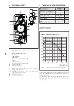
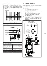
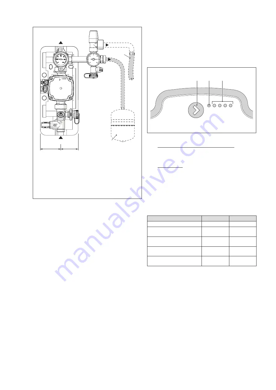
11  WATER CONNECTIONS

T

E

R

RB

SV

VE

60mm

72mm

R


Solar circuit return (3/4" M). Outlet of heat transfer 

fluid towards solar collector.

RB


Storage system return (3/4" M). Inlet of heat trans-

fer fluid from solar storage system.

SV


Safety valve drain

VE


Expansion tank fitting

E


Solar expansion tank (not supplied)

T


Safety valve outlet pipe (not supplied)

-  Connect the return fitting (R)in the upper part of the 

solar station to the solar plant

-  Connect the return fitting (RB)in the lower part of the 

solar station to the accumulation system

-  Connect the safety valve drain to a pipe (T) to avoid 

burns from expelled fluid and to permit the heat trans-

fer fluid to be recovered

-  Connect expansion tank (E), suitable for solar plant 

applications, to 1/2” fitting (VE).

Fasten expansion tank as explained in the instruction 

sheet supplied with the accessory.

For hydraulic connections, use silicone seals having 

a hardness of at least 80SH. If no seals can be used, 

seal fittings with high-temperature sealant (>180°C) 

suitable for solar applications.
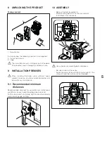
12  PUMP CONTROLLER

The circulator is produced with maximum idraulic head 

configuration of 7,5 meter.

USER INTERFACE

The user interface consists of a push-button (1), a red/

green LED (2) and four yellow LEDs (3).

1

2

3

LED 1 LED 2 LED 3 LED 4 LED 5

When necessary, the user interface provides access to:

-  Functioning (performance display) mode. Pump per-

formance is displayed during functioning as a % of 

current draw with respect to rated load. Alarm condi-

tions can be seen from the colour of LED.

-  Setting Mode: Press button (1) to enter setting mode 

and select the type of pump curve.

FUNCTIONING MODE

Performance display

When the pump is running, LED 1 is green. The four yellow 

LEDs indicate the pump's instantaneous electrical power 

consumption as shown in the table.

Nr. displayed

Meaning

% power

LED 1 flashing green

Stand-by

0

LED 1 green and LED 2 

yellow, both lit

Low load

0-25

LED 1 green and LEDs 2, 3 

yellow, all lit

Low-medium 

load

25-50

LED 1 green, LEDs 2, 3, 4 

yellow, all lit

Medium-high 

load

50-75

LED 1 green, LEDs 2, 3, 4, 

5 yellow, all lit

High load

75-100

Summary of Contents for SOL R-7,5M

Page 1: ...SOLAR STATION SOL R 7 5M INSTALLATION AND MAINTENANCE MANUAL ...

Page 2: ... qualified heating engineer b This instruction manual is an integral part of the prod uct It must be kept safe and must ALWAYS accom pany the product even if it is sold to another owner or transferred to another user or to another installation If you lose this manual order a replacement immedi ately Keep the product purchase documents to be presented to the S authorised Technical Assis tance Centr...

Page 3: ...pervised a Do not dispose of packaging material into the envi ronment or leave it within the reach of children since it can become a potential hazard Dispose of packag ing material in compliance with applicable legislation 3 DESCRIPTION OF THE APPLIANCE The solar station SOL R allows transferring sun power from collectors to a storage system The solar station S is enclosed in a PPE Polypropylene f...

Page 4: ...fitting 7 TECHNICAL SPECIFICATIONS DESCRIPTION return solar station Maximum working pressure 6 bar Maximum operating temper ature 110 C Dimensions LxHxP 264x362x215 mm Net weight with insulation 3 8 kg Power supply 230 50 V Hz Min max electrical current draw 0 04 0 48 A Min Max power consumption 2 45 W Useful head available Return solar station USEFUL HEAD AVAILABLE mbar 800 700 600 0 500 400 300 ...

Page 5: ... to permit easy maintenance 9 1 Recommended minimum distances Recommended distances for assembly and maintenance are 300 mm on each side including expansion tank Put the solar station at a proper hight to allow thermometer and pressure gauge reading 0 3 m 0 3 m 0 3 m Installation 10 ASSEMBLY Remove the front insulation 1 Mark mounting points F on the wall and drill Insert blocks not supplied F F 7...

Page 6: ...ls can be used seal fittings with high temperature sealant 180 C suitable for solar applications 12 PUMP CONTROLLER The circulator is produced with maximum idraulic head configuration of 7 5 meter USER INTERFACE The user interface consists of a push button 1 a red green LED 2 and four yellow LEDs 3 1 2 3 LED 1 LED 2 LED 3 LED 4 LED 5 When necessary the user interface provides access to Functioning...

Page 7: ...or an external control if green it indicates the circulator performance or internal control possibility Led n 2 and 3 indicate different control mode possibility and led n 4 and 5 indicate the curve type setting 1 2 3 o 4 These leds are yellow PWM mode LED 1 LED 2 LED 3 LED 4 LED 5 Curve 1 4 5m Red Yel low Curve 2 5 5m Red Yel low Yel low Curve 3 6 5m Red Yel low Yel low Yel low Curve 4 7 5m Red Y...

Page 8: ...own in the figure PWM CONNECTOR POWER SUPPLY To control the circulator in on off mode the PWM cable is not required To control the circulator in modulating mode by using a solar regulator verify the compatibility between the chosen regu lator and the PWM signal see following paragraph CON TROL SIGNALS CONTROL SIGNALS The circulator can be controlled with a low voltage PWM digital signal pulse widt...

Page 9: ...UiL 1 V Input signal current IiH 10 mA Input Duty cycle PWM 0 100 14 SYSTEM FLUSHING Before filling the system with mixture of water and glycol it is necessary to flush the pipes of the solar system to elimi nate all residues of fluid or scale Proceed as follows Verify the flow meter C is completely open Turn handle on valve VR clockwise Open taps A and B on the return tube Flush water in through ...

Page 10: ...ol and water PC PC Heat transfer fluid filling pump To fill the system proceed as follows Verify the flow meter C is completely open Connect the filling pump PC as shown Turn handle on valve VR clockwise Open taps A and B on the return tube Open manual degassing tap and any bleeder valve located at the highest points of the system and keep them open throughout the filling procedure Pump the heat t...

Page 11: ...afety data sheet supplied with the glycol 17 2 Disassembling the circulator b Remove the circulator when system has cooled down Before removing circulator C Cut power off to the solar station and to the connect ed integration system by setting the system s main switch and the device s main switch to OFF Disconnect circulator power by removing connectors D and E Move away any wiring and electric de...

Page 12: ...ento 23 A 23900 Lecco LC www sylber it The manufacturer strives to continuously improve all products Appearance dimensions technical specifications standard equipment and accessories are therefore liable to modification without notice ...

Reviews: