8
INSTALLATION
13 ELECTRICAL CONNECTIONS
b
The following is mandatory:
- have an omnipolar magneto-thermal circuit breaker
and a disconnecting switch compliant with the pre-
vailing standards of the installation country
- respect the polarity of the L1 (Phase) - N (Neutral)
connections
- use cables with insulation and cross section con-
forming to applicable standards (minimum cross
section 1.5 mm
2
)
- refer to the wiring diagrams in this manual for all
electric operations
- make sure the appliance is connected to an efficient
ground (earth).
a
It is strictly forbidden to use pipes of any kind to
ground the appliance.
The manufacturer is not responsible for damages due
to the device grounding lack.
Refer to the manual supplied with the solar controller
for details of all electrical connections, programming,
etc..
The electricity and PWM signal connections must be ar-
ranged by the technician.
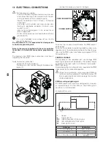
To do the electric connections
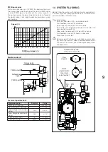
- remove the frontal insulation (1).
- the cables must be inserted through the proper pas-
sages (F).
1
F
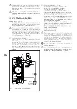
- connect the cables as shown in the figure.
PWM CONNECTOR
POWER SUPPLY
To control the circulator in on/off mode, the PWM cable is
not required.
To control the circulator in modulating mode by using a solar
regulator, verify the compatibility between the chosen regu-
lator and the PWM signal (see following paragraph "CON-
CONTROL SIGNALS
The circulator can be controlled with a low voltage PWM
digital signal (pulse width modulation). The speed changes
according to the input signal, as indicated in paragraph "
Here below are the main characteristics required of the PWM
signal output by the associated regulator.
b
Check the characteristics of your regulator PWM sig-
nal to ensure they comply with the features below. Dif-
ferent signals could irreversibly damage the circulator
on-board electronics.
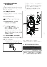
PWM low-voltage digital signal
The PWM square wave signal was designed for a frequen-
cy interval between 100 and 4000 Hz. The PWM signal is
used to set circulator speed.
Example of Duty cycle
T
U
iH
U
iL
t
T
Period
d
Duty cycle (t/T)
UiH
High voltage level of input signal
UiL
Low voltage level of input signal
IiH
Input signal current
Example
Evaluation
T = 2 ms (500 Hz)
UiH = 4-24 V
t = 0,6 ms
UiL ≤ 1 V
d % = 100 x 0.6 / 2 = 30 % IiH ≤ 10 mA (depending
on UiH)


