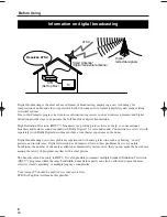
11
EN
1A23
Antenna Connections
2 Antenna
Connections
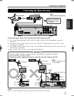
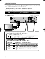
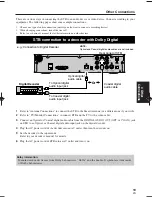
Before connecting, ensure the AC power cord is NOT connected to the AC outlet.
To connect the Smart Antenna, refer to your Smart Antenna’s manual for details.
1
Use a 75 ohm coaxial antenna cable to connect the Smart Antenna to the TO ANTENNA jack on the
control box.
2
Use another 75 ohm coaxial antenna cable to connect the TO TV (STB) jack on the control box to the
ANT. IN jack on the STB.
3
Use the Smart Antenna control cable to connect the ANTENNA CONTROL jack on the control box to the
ANT. CTL jack on the STB.
4
Refer to pages 14-21 to connect to your audiovisual equipment.
D. AU D I O O U T
C O A X .
L
P b
P r
L
R
1
2
Y
C V B S
O U T
C O M P.
O U T
A N T.
C T L
D. AU D I O
O U T
DV I COMP.
DV I - D H D C P O U T
OPT
S - V I D E O
O U T
RESOLUTION
SELECT
1 0 8 0 i / 7 2 0 p / 4 8 0 p
A N T. I N
AU D I O O U T
Rear panel of STB
NOTE:
Antenna cable is not included.
Control box
Smart Antenna
Refer to your Smart
Antenna’s manual
for details.
Connecting the Smart Antenna
CAUTION
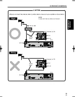
The charactoristics of the Smart Antenna mean it is only suitable for connection to one STB.
Connect one STB to one Smart Antenna.
Do not connect other equipment between the control box, the Smart Antenna and STB.
NOTE:
Antenna and Antenna cable
are not included.
A N T.
C T L
DV I - D H D C P O U T
A N T. I N
Right
ANT. IN
ANT. CTL
Antenna
cable
Smart Antenna
Antenna
cable
Antenna
control
cable
STB
Control
box
D. AU D I O O U T
C O A X .
L
P b
P r
L
R
1
2
Y
C V B S
O U T
C O M P.
O U T
A N T.
C T L
D. AU D I O
O U T
DV I COMP.
DV I - D H D C P O U T
OPT
S - V I D E O
O U T
RESOLUTION
SELECT
1 0 8 0 i / 7 2 0 p / 4 8 0 p
A N T. I N
AU D I O O U T
ANT. CTL
Wrong
e.g.:
Connection to VCR
ANT. IN
RF-IN
RF-OUT
Antenna cable
Smart Antenna
Antenna
cable
Antenna
cable
STB
Control
box
Splitter
Antenna
control
cable
NOTE:
If unit is not connected properly according to diagram unit may experience power failure.
ST300UA.qxd 04.8.3 1:12 PM Page 11


