1. GENERAL INFORMATION/TROUBLE DIAGNOSIS
SYM
1-10
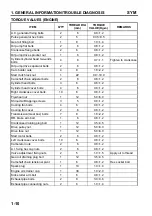
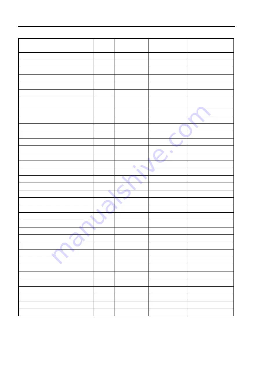
TORQUE VALUES (ENGINE)
ITEM Q'TY
THREAD DIA
(mm)
TORQUE
VALUE(Kg-m)
REMARKS
A.C. generator fixing bolts
2
6
0.8~1.2
Pulse generator hex bolts
2
5
0.35~0.5
Gear oil filling bolt
1
8
1.0~1.4
Oil pump flat bolts
2
6
0.8~1.2
Crankcase flange bolts
2
6
0.8~1.2
Oil pump drive sprocket nut
1
6
0.8~1.2
Cylinder/cylinder head two-ends
bolts
4
8
0.7~1.1
Tighten to crankcase
Oil pump drive separator bolts
2
6
0.8~1.2
Cam holder nuts
4
8
1.8~2.2
Start clutch lock nut
1
22
9.0~10.0
Camshaft chain adjuster bolts
2
6
0.8~1.2
Cylinder head bolts
3
6
0.8~1.2
Cylinder head cover bolts
4
6
0.8~1.2
Right crankcase cover bolts
10
6
0.8~1.2
Flywheel nut
1
12
5.0~6.0
Shroud A/B tapping screws
3
5
0.8~1.2
Cooling fan bolts
4
6
0.8~1.2
Cooling fan cover
2
6
0.8~1.2
Transmission(Gear box) bolts
7
8
1.8~2.2
RR. brake arm bolt
1
6
0.8~1.2
Crankcase draining plug bolt
1
12
3.5~4.5
Drive pulley nut
1
12
5.0~6.0
Drive face nut
1
12
5.0~6.0
Start motor bolts
2
6
0.8~1.2
Left crankcase cover bolts
10
6
0.8~1.2
Carburetor nuts
2
6
0.8~1.2
A.I. fixing hex cap nuts
2
6
0.8~1.2
Valve adjustment fixing nuts
2
5
1.0~1.5
Apply oil to thread
Gear oil draining plug bolt
1
12
3.5~4.5
Camshaft chain tensioner pivot
1
6
0.8~1.2
Hex socket bolt
Spark plug
1
10
1.0~1.4
Engine oil strainer cap
1
30
1.0~2.0
Kick starter arm bolt
1
6
0.8~1.2
Exhaust pipe bolts
2
8
3.0~3.6
Exhaust pipe connecting nuts
2
6
1.0~1.4
Summary of Contents for ALA125CC
Page 45: ...SYM 13 BRAKE 13 3 MECHANISM DIAGRAM Rear Drum Brake System 0 8 1 2 kgf m 0 8 1 2 kgf m...
Page 93: ......
Page 176: ...SERVICE MANUAL...


