6. CYLINDER HEAD/VALVE SYM
6-14
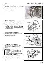
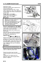
Install the lock pins.
Install the camshaft holder, gasket and nut
onto the cylinder head.
Tighten the cylinder head nuts. (4 nuts)
At first, tighten the 4 nuts on the cylinder top
and then tighten the 2 bolts on the left side of
cylinder head.
Torque value: 1.8~2.2 kgf-m
Install the spark plug and tighten it.
Torque value: 1.0~1.4 kgf-m
Caution
VALVE CLEARANCE ADJUSTMENT
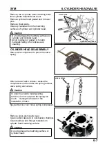
Loosen valve clearance adjustment nuts and
bolts located on valve rocker arm.
Measure and adjust valve clearance with
feeler gauge.
After valve clearance had been adjusted to
standard value, hold adjustment bolt and
then tighten the adjustment nut.
Standard Value:
0.12
±
0.02/ 0.12
±
0.02 mm
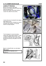
With flat screwdriver, turn the cam sprocket
adjuster in counter-clockwise motion so that
the adjuster is pushed out to contact the cam
chain plate tightly. Apply with oil onto a new
O-ring and then install it onto the adjuster
hole. Tighten the bolt cap of the adjuster
adjustment hole.
Caution
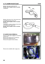
Replace the O-ring of the cylinder head with
new one. Install the cylinder head.
Tighten the cylinder head lock bolts.
Connect the blow-by hose onto the cylinder
head.
Tighten the 2
nd
air injection (AI) nut.
Install the engine onto the engine frame.
(Refer to Chapter 5)
Apply with oil onto the thread of cylinder
head bolts and tighten the bolts in
diagonally for 2-3 sequences.
Do not over tightening the bolts to avoid
the cylinder head deformation, noise
created or leaking so that effects
motorcycle’s performance.
The O-ring must be installed into glove.
pin
holder
Especial tool
Blow-by hose
4 bolts
A.I
Summary of Contents for ALA125CC
Page 45: ...SYM 13 BRAKE 13 3 MECHANISM DIAGRAM Rear Drum Brake System 0 8 1 2 kgf m 0 8 1 2 kgf m...
Page 93: ......
Page 176: ...SERVICE MANUAL...

