SYM 8. V-BELT DRIVING SYSTEM/KICK STARTER ARM
8-9
CLUTCH/DRIVEN PULLEY
DISASSEMBLY
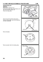
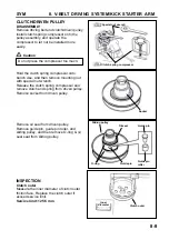
Remove driving belt and clutch/driven pulley.
Install clutch spring compressor onto the
pulley assembly, and operate the
compressor to let nut be installed more
easily.
Caution
Hold the clutch spring compressor onto
bench vise, and then remove mounting nut
with special nut wrench.
Release the clutch spring compressor and
remove clutch and spring from driven pulley.
Remove socket from driven pulley.
Remove oil seal from driven pulley.
Remove guide pin, guide pin roller, and
sliding pulley, and then remove O-ring & oil
seal seat from sliding pulley.
INSPECTION
Clutch outer
Measure the inner diameter of clutch outer
friction face. Replace the clutch outer if
exceed service limit.
Service limit: 125.5 mm
Do not press the compressor too much.
Clutch outer
Inner
diameter
O-ring
Guide pin
Guide pin
roller
Guide pin
Oil seal
Sliding pulley
Socket
Clutch spring compressor
Special nut wrench
Summary of Contents for ALA125CC
Page 45: ...SYM 13 BRAKE 13 3 MECHANISM DIAGRAM Rear Drum Brake System 0 8 1 2 kgf m 0 8 1 2 kgf m...
Page 93: ......
Page 176: ...SERVICE MANUAL...


