12. BODY COVER SYM
12-4
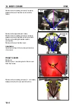
Remove the mounting screws (2 screws)
between the rear handle cover and the
frame.
Remove the speedometer cable.
Remove the mounting screws (4 screws)
between the rear handle cover and meter.
Remove the left/right handle switch
connectors.
Remove the rear handle cover.
Installation:
Install according to the reverse procedure
of removal.
FRONT COVER
Removal
Remove the 1 mounting bolt of front cover
from the frame.
Remove the mounting screws (3
×
2 screws)
between the front cover and inner box.
screws
×
2
left
right
screws
×
4
speedometer
cable
bolt
×
1
6 screws
Summary of Contents for ALA125CC
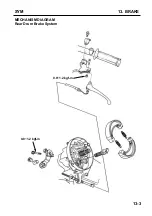
Page 45: ...SYM 13 BRAKE 13 3 MECHANISM DIAGRAM Rear Drum Brake System 0 8 1 2 kgf m 0 8 1 2 kgf m...
Page 93: ......
Page 176: ...SERVICE MANUAL...

