SYM 12. BODY COVER
12-5
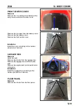
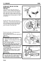
Remove the front turn left/right signal light
wire connectors.
Remove the front cover.
Installation:
Install according to the reverse procedure of
removal.
UNDER COVER
Removal
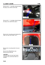
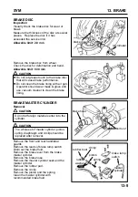
Remove the 1
×
2 mounting screws between
the left/right side cover and the floor panel.
Remove the 1
×
2 mounting screws between
the left/right side cover and the frame.
Remove the 2
×
2 mounting bolts between
the under cover and the frame.
Remove the under cover.
Installation:
Install according to the reverse procedure of
removal.
wire connectors
1
×
2 screws
1
×
2 screws
2
×
2 bolts
Summary of Contents for ALA125CC
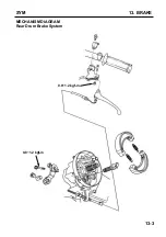
Page 45: ...SYM 13 BRAKE 13 3 MECHANISM DIAGRAM Rear Drum Brake System 0 8 1 2 kgf m 0 8 1 2 kgf m...
Page 93: ......
Page 176: ...SERVICE MANUAL...

