SYM 14. STEERING/FRONT WHEEL/FRONT SHOCK ABSORBER
14-3
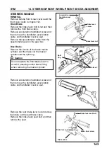
STEERING HANDLE
REMOVAL
Remove handle front & rear covers and the
front cover (refer to chapter 12).
Drum Brake
Remove the brake lever bolt & nut and then
remove the front brake cable.
Remove acceleration handlebar screw and
then remove the handlebar, acceleration
cable, and handlebar cover & seat.
Remove the speedometer cable from the
speedometer gear on the gear box.
Disc Brake
Remove the 2 bolts of the brake master
cylinder, and then take out the master
cylinder and the split ring.
Caution
Remove acceleration handlebar screw and
then remove the handlebar, acceleration
cable, and handlebar cover & seat.
Remove the rear brake lever nut and screw,
then take out the rear brake cable.
Remove the brake lever seat bolt, and then
remove the seat.
Do not operate the front brake lever to
avoid to pressing out the brake lining
when removing the master cylinder.
Acceleration
handlebar seat
screw
Brake lever
screw
Brake lever nut
Screw
Bolts x 2
Master cylinder
Split
ring
Seat
Brake cable
Brake lever seat bolt
Brake lever screw
Brake lever nut
Summary of Contents for ALA125CC
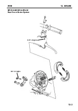
Page 45: ...SYM 13 BRAKE 13 3 MECHANISM DIAGRAM Rear Drum Brake System 0 8 1 2 kgf m 0 8 1 2 kgf m...
Page 93: ......
Page 176: ...SERVICE MANUAL...

