16. ELECTRICAL EQUIPMENT SYM
16-2
PRECAUTIONS IN OPERATION
Charging System
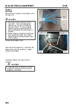
When remove the battery, the disconnection sequence of cable terminals shall be strictly observed.
(First disconnect the negative cable terminal, next, the positive cable terminal.)
MF (Maintenance Free) battery does not need to check, add electrolyte or distilled water.
Battery must be taken out from scooter when charging the battery. But do not open the battery caps.
Do not quick charge the battery unless in emergency.
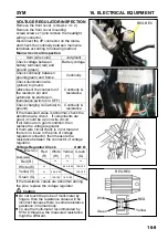
A voltmeter must be used when checking battery charging condition.
Battery can be charged or discharged alternately. To set a discharged battery idle for a prolonged
period will shorten its service life and reduce its capacity. Usually, battery’s capacity will reduce after
1~2 years. After low capacity battery was charged, its voltage will increase. If it connects to an
additional load, the voltage will reduce suddenly, and then go up again.
Over-charged battery. Usually, the over-charged battery can be seen externally. If a short circuit
occurred inside the battery, there will be no voltage on the terminals of battery if voltage regulator does
not operate. Then, the battery’s voltage will be too high that may reduce battery’s life.
The battery will be self-discharged if it was set idle for a long time. An idle battery must be charged
about every 2months.
A new battery filled with electrolyte will generate a voltage after filled out electrolyte. The voltage
should be in 12.5V or more after 10 minutes. When electrolyte is not enough, the battery must be filled
with electrolyte and then charged to prolong the battery’s life-span.
Please check electrical device according to the procedure of diagnosis chart.
Do not disconnect and connect the connector of electrical devices when current is passing these
devices because this will generate high voltage and the electrical components in the voltage-current
regulator will be damaged. The ignition switch must be turned OFF before performing any work.
Please do not replace with traditional type battery as replacement.
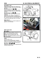
Please refer to the removal instruction when removing the alternator and the pulse generator.
Ignition System
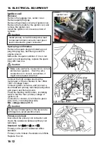
Please follow the procedure of trouble diagnosis chart to check ignition system.
The ignition system equipped with a auto-advanced timing device in CDI unit. Thus, ignition timing
need not to be adjusted. In case of incorrect ignition timing occurred, check the CDI unit or alternator
system. It has to check the ignition timing with the ignition timing light if replaced these components.
Do not hang or impact the CDI unit of ignition system because the major faulty of CDI unit is caused by
impact. Therefore, take care when disassembling.
Most of ignition system problems were resulted from poor connecting connector. Please check the
connectors first when servicing.
Make sure that the heat range of spark plug is suitable. Improper spark plug is the main cause of poor
engine operation or combustion.
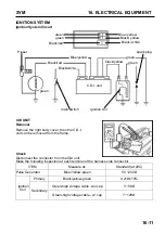
Inspection procedures in this manual are based on Max. voltage. This manual also contains methods
of how to check ignition coil resistance and component operation.
Please follow the continuity chart to check ignition switch.
Starting System
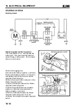
Starting motor can be removed directly from engine.
Please refer to chapter 10 for starting clutch removal procedures.
Summary of Contents for ALA125CC
Page 45: ...SYM 13 BRAKE 13 3 MECHANISM DIAGRAM Rear Drum Brake System 0 8 1 2 kgf m 0 8 1 2 kgf m...
Page 93: ......
Page 176: ...SERVICE MANUAL...

