5
. Removal & Installation of Engine
5-1
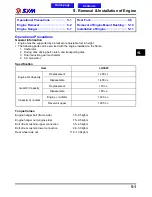
Operational Precautions€€€€€€€€€€€€€€€€€€€€€ 5-1
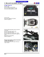
Engine Removal €€€€€€€€€€€€€€€€€€€€€€€€€€€€€€€€€€ 5-2
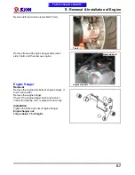
Engine Hanger €€€€€€€€€€€€€€€€€€€€€€€€€€€€€€€€€€€€€ 5-7
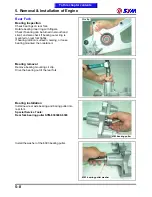
Rear Fork €€€€€€€€€€€€€€€€€€€€€€€€€€€€€€€€€€€€€€€€€€€€€€ 5-8
Removal of Engine Mount Bushing€€€€ 5-10
Installation of Engine€€€€€€€€€€€€€€€€€€€€€€€€€€€ 5-11
Operational Precautions
General Information
Engine must be supported by a bracket or adjustable tool in height.
The following parts can be serviced with the engine installed on the frame.
1. Carburetor.
2. Driving disk, driving belt, clutch, and transporting disk.
3. Final reduction gear mechanism.
4. AC. Generator.
Specification
Item
LH30W
Replacement
1,200 c.c.
Engine Oil Capacity
Disassemble
1,400 c.c.
Replacement
170 c.c.
Gear Oil Capacity
Disassemble
180 c.c.
radiator
1400 c.c.
Capacity of coolant
Reservoir upper
1200 c.c.
Torque Values
Engine hanger bolt (frame side)
7.5~9.5kgf-m
Engine hanger nut (engine side)
7.5~9.5kgf-m
Bolt of rear cushion upper connection
3.5~4.5kgf-m
Bolt of rear cushion lower connection
2.4~3.0kgf-m
Rear wheel axle nut
11.0~13.0kgf-m
5
Home page
Contents
Summary of Contents for Citycom.300i
Page 5: ...Serial Number Home page Contents...
Page 38: ...2 Maintenance Information 2 17 Note To this chapter contents...
Page 46: ...3 LUBRICATION SYSTEM 3 8 Notes To this chapter contents...
Page 106: ...4 Fuel Injection System 4 60 Note To this chapter contents...
Page 173: ...10 AC Generator Starting Clutch 10 10 Notes To this chapter contents...
Page 195: ...12 Cooling System 12 14 Notes To this chapter contents...
Page 223: ...14 Brake System 14 12 Note To this chapter contents...
Page 244: ...17 Electrical System 17 5 FUSE Fuse circuit diagram To this chapter contents...
Page 262: ...17 Electrical System 17 23 Note To this chapter contents...
Page 270: ...19 Electrical Diagram 19 1 Home page Contents LH30W EFi Electrical Diagram 19...


