12. Cooling System
12-13
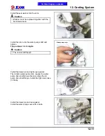
Place the thermostat into heated water to check its
operation.
Caution
Whenever the thermostat and the
thermometer are in contact to the wall of
heated water container, the reading
displayed is incorrect. If the valve of the
thermostat remains open at room
temperature or the valve operation is not
corresponding to the temperature change,
then it must be replaced.
Technical Data
Valve begins to open
82~95℃
Valve stroke
0.05 ~ 3mm
Installation
Install the thermostat.
Install the thermostat cover. (2 bolts)
Refill the coolant and bleed out the air bubble
(Page 12-5).
2 bolts
To this chapter contents
Summary of Contents for Citycom.300i
Page 5: ...Serial Number Home page Contents...
Page 38: ...2 Maintenance Information 2 17 Note To this chapter contents...
Page 46: ...3 LUBRICATION SYSTEM 3 8 Notes To this chapter contents...
Page 106: ...4 Fuel Injection System 4 60 Note To this chapter contents...
Page 173: ...10 AC Generator Starting Clutch 10 10 Notes To this chapter contents...
Page 195: ...12 Cooling System 12 14 Notes To this chapter contents...
Page 223: ...14 Brake System 14 12 Note To this chapter contents...
Page 244: ...17 Electrical System 17 5 FUSE Fuse circuit diagram To this chapter contents...
Page 262: ...17 Electrical System 17 23 Note To this chapter contents...
Page 270: ...19 Electrical Diagram 19 1 Home page Contents LH30W EFi Electrical Diagram 19...


