17. Electrical System
17-18
Switch / Horn
Main switch
Inspection
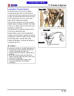
Remove the front cover.
Disconnect the main switch coupler.
Check the continuity between two points as
indicted below
Pin
Position
BAT
BAT1
BAT2
LOCK
OFF
ON
Wire Color
Red
Black
Blake
Replacement of main switch
Remove main switch cap. (1 bolt).
Disconnect the coupler of the main switch and
loosen the mounting bolts (2 bolts).
Remove the main switch.
Install the new main switch and tighten the
mounting bolts.
Install the main switch coupler and cap.
Right handle switch
Remove the handle cover and front cover.
Disconnect the coupler of right handle switch.
Check the continuity between two points as
indicated in the table below
Headlight switch
Pin
Position
TL
CI
HL
CI
●
Wire Color
Brown Black
Black
Blue
/White
Start and engine stop switch
Pin
Position
ST
E
ST
E
FREE
Wire Color
Black
Black
/Green
Yellow
/ Red
Sky blue/
Orange
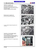
1 blot
Start switch
Headlight switch
Engine stop switch
Main switch coupler
To this chapter contents
2 blots
Right handle switch coupler
Summary of Contents for Citycom.300i
Page 5: ...Serial Number Home page Contents...
Page 38: ...2 Maintenance Information 2 17 Note To this chapter contents...
Page 46: ...3 LUBRICATION SYSTEM 3 8 Notes To this chapter contents...
Page 106: ...4 Fuel Injection System 4 60 Note To this chapter contents...
Page 173: ...10 AC Generator Starting Clutch 10 10 Notes To this chapter contents...
Page 195: ...12 Cooling System 12 14 Notes To this chapter contents...
Page 223: ...14 Brake System 14 12 Note To this chapter contents...
Page 244: ...17 Electrical System 17 5 FUSE Fuse circuit diagram To this chapter contents...
Page 262: ...17 Electrical System 17 23 Note To this chapter contents...
Page 270: ...19 Electrical Diagram 19 1 Home page Contents LH30W EFi Electrical Diagram 19...

