4. Fuel Injection System
4-3
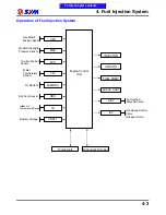
Operation of Fuel Injection System
Engine Control
Unit
CPS
MAP
TPS
ROS
LAMBDA
TA
TW
Water
Temperature
Sensor
O
2
Sensor
Roll Over Sensor
Throttle Position
Sensor
Manifold Absolute
Pressure Sensor
Crankshaft
Position Sensor
INJECTOR
IGN COIL
FUEL PUMP
CHECK LIGHT
Tuning tools
Diagnostic Scanner
VBATT
Battery Voltage
Intake Air
Temperature Sensor
AISV
Air Injection
Solenoid Valve
ISC
Idle Speed Control
Valve
(Stepper motor)
To this chapter contents
Summary of Contents for Citycom.300i
Page 5: ...Serial Number Home page Contents...
Page 38: ...2 Maintenance Information 2 17 Note To this chapter contents...
Page 46: ...3 LUBRICATION SYSTEM 3 8 Notes To this chapter contents...
Page 106: ...4 Fuel Injection System 4 60 Note To this chapter contents...
Page 173: ...10 AC Generator Starting Clutch 10 10 Notes To this chapter contents...
Page 195: ...12 Cooling System 12 14 Notes To this chapter contents...
Page 223: ...14 Brake System 14 12 Note To this chapter contents...
Page 244: ...17 Electrical System 17 5 FUSE Fuse circuit diagram To this chapter contents...
Page 262: ...17 Electrical System 17 23 Note To this chapter contents...
Page 270: ...19 Electrical Diagram 19 1 Home page Contents LH30W EFi Electrical Diagram 19...


