4. Fuel Injection System
4-17
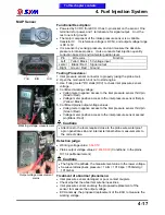
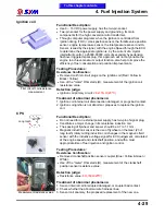
MAP Sensor
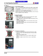
Working voltage
measurement
Output voltage measurement
plains
Functional Description:
●
Powered by 5V DC from ECU. It has 3-pin socket on the sensor. One
terminal is for power, and 1 terminal are for signal output. And, the
rest one is for ground.
●
The major component of the intake pressure sensor is a variable
transistor IC. Its reference voltage is DC 5V, and output voltage range
is DC 0~5V.
●
It is a sensor by sensing pressure, and can measure the absolute
pressure in intake process. It also conducts fuel injection quantity
correction based on environmental position level.
Pin
Wire color
Function
Left
Yellor / Black
5V voltage input
center
Black / Red
Signal output
Right
Green / Red
Ground
Testing Procedures:
1. Inlet pressure sensor connector to properly (using the probe tool).
2. Open the main switch, but not to start engine.
3. Use "volteg meter" DC stalls (DCV) to check inlet pressure sensor
voltage.
4. Confirmed working voltage:
●
Volteg meter negative access to the inlet pressure sensor third pin
(Green / Red).
●
Voltage meter positive access to the inlet pressure sensor first pin
(Yellow / Black).
5. Confirmed plains output voltage values:
●
Volteg meter negative access to the inlet pressure sensor third pin
(Green / Red).
●
Voltage meter positive access to the inlet pressure sensor second
pin (Black / Red)
Cautions
●
Attentions to the tools required close to the probe wire waterproof
apron penetrate skin and internal terminal before measurements to
the correct value.
Detection judge:
●
Working voltage value:
5.0
‰
0.1V
●
Plains output voltage values:
2.87
‰
0.03V
(Conditions: In the plains
101.3 kpa Measurement)
Cautions
●
The higher the altitude, the measurement value to the lower voltage.
●
Sea-level atmospheric pressure = 1Atm = 101.3kpa = 760mmHg =
1013mbar
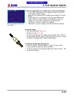
Treatment of abnormal phenomena:
●
Inlet pressure sensor damaged, or poor contact couplers.
●
Check whether the abnormal wire harness lines.
●
Inlet pressure sensor anomaly, the proposed replacement of the
sensor to measure the output voltage.
●
ECU anomaly, the proposed replacement of the ECU to measure the
working voltage.
Y/B
B/R
G/R
To this chapter contents
Summary of Contents for Citycom.300i
Page 5: ...Serial Number Home page Contents...
Page 38: ...2 Maintenance Information 2 17 Note To this chapter contents...
Page 46: ...3 LUBRICATION SYSTEM 3 8 Notes To this chapter contents...
Page 106: ...4 Fuel Injection System 4 60 Note To this chapter contents...
Page 173: ...10 AC Generator Starting Clutch 10 10 Notes To this chapter contents...
Page 195: ...12 Cooling System 12 14 Notes To this chapter contents...
Page 223: ...14 Brake System 14 12 Note To this chapter contents...
Page 244: ...17 Electrical System 17 5 FUSE Fuse circuit diagram To this chapter contents...
Page 262: ...17 Electrical System 17 23 Note To this chapter contents...
Page 270: ...19 Electrical Diagram 19 1 Home page Contents LH30W EFi Electrical Diagram 19...

