4. Fuel Injection System
4-28
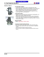
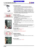
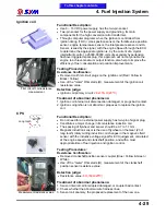
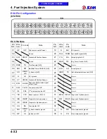
Fuel Injector
Injector r
esistance confirmation
Injection-state
atomizing good
Injection-state unusual
Functional Description:
●
Powered by DC 8~16V, and has two-pin socket on the injector.
●
Its major component is the solenoid valve of high resistance driven by
electronic current.
●
The two terminals are connected to power source and ground
respective. It is controlled by ECU to decide the injection timing, and
the injector pulse width.
Testing Procedures:
1. Resistance Confirmation:
Use of the "meter" Ohm stalls (Ω), measurement of the injector
resistance value.
2. Injector injection state examination:
●
Removed the injector fixed bolt and removed the injector from intake
manifold, but not removal of harness coupler.
●
Injector and injector cap tightly by hands, fuel spills should not be
the case.
●
Key-on and start the engine, injector injection state examination.
Detection judge:
1. Between the two pin resistance values:
11.7
‰
0.6
Ω
2. injection state:
●
Fuel atomizing good, with a clear scattering angle → judged as
normal.
●
Injection-state such as water, no obvious scattering angle → found
abnormal.
Treatment of abnormal phenomena:
1. Injector abnormal, the proposed replacement of the new one injector.
2. Injection-state abnormal, for the following reasons:
●
Injector obstructive
→
the proposed replacement of the new one
injector.
●
Fuel pressure shortage → confirmed hydraulic pressure, the
proposed replacement fuel pump to confirm.
Warning
●
Gasoline is lower ignited explosive materials, in the ventilation
premises operations, and prohibited fire.
●
In the inspection injector fuel injection state, the outflow of gasoline,
and the application of appropriate collection containers, so as to
avoid danger.
To this chapter contents
Summary of Contents for Citycom.300i
Page 5: ...Serial Number Home page Contents...
Page 38: ...2 Maintenance Information 2 17 Note To this chapter contents...
Page 46: ...3 LUBRICATION SYSTEM 3 8 Notes To this chapter contents...
Page 106: ...4 Fuel Injection System 4 60 Note To this chapter contents...
Page 173: ...10 AC Generator Starting Clutch 10 10 Notes To this chapter contents...
Page 195: ...12 Cooling System 12 14 Notes To this chapter contents...
Page 223: ...14 Brake System 14 12 Note To this chapter contents...
Page 244: ...17 Electrical System 17 5 FUSE Fuse circuit diagram To this chapter contents...
Page 262: ...17 Electrical System 17 23 Note To this chapter contents...
Page 270: ...19 Electrical Diagram 19 1 Home page Contents LH30W EFi Electrical Diagram 19...

