5. CYLINDER HEAD/CYLINDER/PISTON
5-6
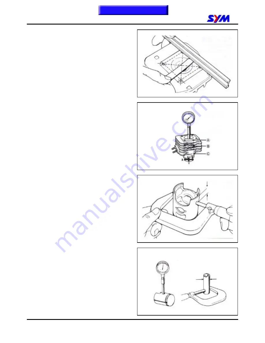
Use a straight edge and a feeler gauge to
measure the cylinder head for warp.
Service limit: 0.10 mm
In “X” and “Y” direction, measure the cylinder for
worn out as the three levels shown in the figure.
With the max. value to decide cylinder wear out
condition.
Service limit : 39.05mm
Measure the OD of piston at the 7 mm from the
bottom of the piston.
Service limit : 38.935 mm
Calculate the clearance between piston and
cylinder.
Service limit: 0.100 mm
Measure the ID of piston pin hole.
Service limit : 12.030mm
Measure the OD of piston pin.
Service limit : 11.970 mm
The ID of piston pin hole
The OD of piston pin
7mm
This chapter Contents
Summary of Contents for DD 50
Page 1: ...DD 50 SERVICE MANUAL FORWARD HOW TO USE THIS MANUAL CONTENTS MECHANISM ILLUSTRATIONS...
Page 6: ...MODEL ILLUSTRATION FT05T FT05U FT05W Home page Contents...
Page 7: ......
Page 23: ...1 GENERAL INFORMATION 1 16 Note This chapter Contents...
Page 43: ...3 LUBRICATION SYSTEM 3 6 Notes This chapter Contents...
Page 49: ...4 ENGINE REMOVAL 4 6 Note This chapter Contents...
Page 81: ...8 FINAL DRIVING MECHANISM 8 6 Notes This chapter Contents...
Page 97: ...10 FUEL SYSTEM 10 10 Notes This chapter Contents...
Page 99: ...11 BRAKE SYSTEM 11 2 Front Drum Brake System 2 5kgf m 6 0kgf m 0 55kgf m This chapter Contents...
Page 100: ...11 BRAKE SYSTEM 11 3 Rear Drum Brake System 2 5kgf m 11 0kgf m 0 55kgf m This chapter Contents...
Page 123: ...12 BODY COVER 12 14 Note This chapter Contents...
Page 156: ...16 ELECTRICAL DIAGRAM 16 1 DD 50 ELECTRICAL DIAGRAM 16 Home page Contents...
Page 157: ...16 ELECTRICAL DIAGRAM 16 2 Notes Home page Contents...


