11. BRAKE SYSTEM
11-5
Hydraulic Disc Brake
Close the drain valve of the hydraulic disc brake.
Replace the brake fluid.
Before the brake fluid reservoir is removed, turn
the handle so that the brake fluid reservoir
becomes horizontal, then remove the brake fluid
reservoir.
Cover the painted surfaces, plastic or rubber
components with a rag when servicing brake
system.
Caution
Spilled brake fluid on painted surfaces, plastic
or rubber components may result in their
damages.
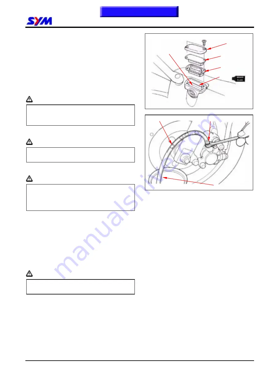
Remove the master cylinder cap and diaphragm.
Use brake fluid to clean the dirty brake disc.
Caution
The dirty brake lining or disc will reduce the
brake performance.
Refill up same grade brake fluid into the
reservoir.
Caution
To mixed non-compatible brake fluid will
reduce brake performance. Foreign materials
will block the system causing brake
performance to be reduced or totally lost.
Connect drain hose to drain valve.
Open the drain valve on the caliper and operate
the brake lever until the old brake fluid is entirely
drained out. Close the drain valve and add
specified brake fluid into the brake master
cylinder.
Recommended brake fluid: WELLRUN DOT 3
brake fluid
Caution
To reuse the spent brake fluid will effect brake
performance.
Connect one end of transparent hose to the
drain valve, and put the other end into a
container.
Open the drain valve around 1/4 turns, and at
the same time hold the brake lever until the
there is no air bubble in the drain hose and also
feeling resistance on the brake lever.
Close the drain valve when finishing the brake
system refilling fluid procedure, and operate the
brake lever to check whether air bubble is in
brake system or not. If brake is still soft,
please bleed the system as described below.
Cap plate
Diaphragm
Upper level
Drain valve
Drain hose
Air bubble
Cap
Lower level
Summary of Contents for Euro 100
Page 1: ...SERVICE MANUAL Forward Contents How To Use This Manual Mechanism Illustrations 50 100 50 100...
Page 7: ......
Page 25: ...1 GENERAL INFORMATION 1 18 Note This chapter Contents...
Page 45: ...3 LUBRICATION SYSTEM 3 6 NOTES This chapter Contents...
Page 81: ...8 FINAL DRIVING MECHANISM 8 6 Notes This chapter Contents...
Page 97: ...10 FUEL SYSTEM 10 10 Notes This chapter Contents...
Page 109: ...11 BRAKE SYSTEM 11 12 Notes This chapter Contents...
Page 121: ...12 BODY COVER 12 12 Note This chapter Contents...
Page 157: ...15 ELECTRICAL EQUIPMENT 15 22 Notes This chapter Contents...
Page 158: ...16 ELECTRICAL DIAGRAM 16 1 JET 50 ELECTRICAL DIAGRAM 16 Home page Contents...
Page 159: ...16 ELECTRICAL DIAGRAM 16 2 JET 50 EURO ELECTRICAL DIAGRAM Home page Contents...
Page 160: ...16 ELECTRICAL DIAGRAM 16 3 JET 100 ELECTRICAL DIAGRAM Home page Contents...
Page 161: ...16 ELECTRICAL DIAGRAM 16 4 Notes Home page Contents...


