11. BRAKE SYSTEM
11-6
Disc Brake -Air Bleed
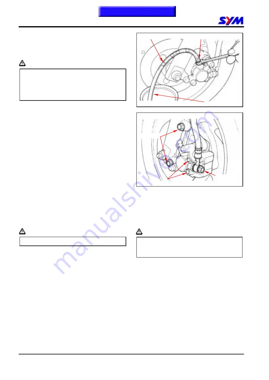
1. Tightly hold the brake lever and open the
drain valve around 1/4 turns, and then close
the valve.
Caution
y
Do not release the brake lever before the
drain valve is closed.
y
Always check the brake fluid level when
carrying out the air bleeding procedure to
avoid air enter into the system.
2. Slowly release the brake lever, and wait for
a few seconds until it reaches its top
position.
3. Repeat the steps 1 and 2 until there is no air
bubble at the end of the hose.
4. Tightly close the drain valve.
5. Make sure the brake fluid is in the UPPER
level of the master cylinder, and refill the
fluid if necessary.
6. Cover the cap.
Disc Brake - Caliper
Removal
Place a container under the brake caliper, and
loosen the brake hose bolt and finally remove
the brake hoses.
Caution
Do not spill brake fluid on painted surfaces.
Remove the bolt cap and loosen the lining guide
bolts.
Remove two caliper bolts and the caliper.
Installation
Install the brake caliper and tighten the attaching
bolts securely.
Torque: 3.3 kgf-m
Caution
y
Use M8 x 35 mm flange bolt only.
y
Long bolt will impair the operation of brake
disc.
Tighten the lining guide bolt.
Torque: 1.8 kgf-m
Install bolt cap.
Torque: 1.0 kgf-m
Use two seal washers and hose bolts to lock the
hose and brake caliper in place.
Torque: 3.5 kgf-m
Refill up the brake fluid to the reservoir and
make necessary air bleeding.
Caliper bolt
Collar bolt
Brake hose
bolt
Drain valve
Drain hose
Air bubble
Summary of Contents for Euro 100
Page 1: ...SERVICE MANUAL Forward Contents How To Use This Manual Mechanism Illustrations 50 100 50 100...
Page 7: ......
Page 25: ...1 GENERAL INFORMATION 1 18 Note This chapter Contents...
Page 45: ...3 LUBRICATION SYSTEM 3 6 NOTES This chapter Contents...
Page 81: ...8 FINAL DRIVING MECHANISM 8 6 Notes This chapter Contents...
Page 97: ...10 FUEL SYSTEM 10 10 Notes This chapter Contents...
Page 109: ...11 BRAKE SYSTEM 11 12 Notes This chapter Contents...
Page 121: ...12 BODY COVER 12 12 Note This chapter Contents...
Page 157: ...15 ELECTRICAL EQUIPMENT 15 22 Notes This chapter Contents...
Page 158: ...16 ELECTRICAL DIAGRAM 16 1 JET 50 ELECTRICAL DIAGRAM 16 Home page Contents...
Page 159: ...16 ELECTRICAL DIAGRAM 16 2 JET 50 EURO ELECTRICAL DIAGRAM Home page Contents...
Page 160: ...16 ELECTRICAL DIAGRAM 16 3 JET 100 ELECTRICAL DIAGRAM Home page Contents...
Page 161: ...16 ELECTRICAL DIAGRAM 16 4 Notes Home page Contents...


