10. FUEL SYSTEM
10-4
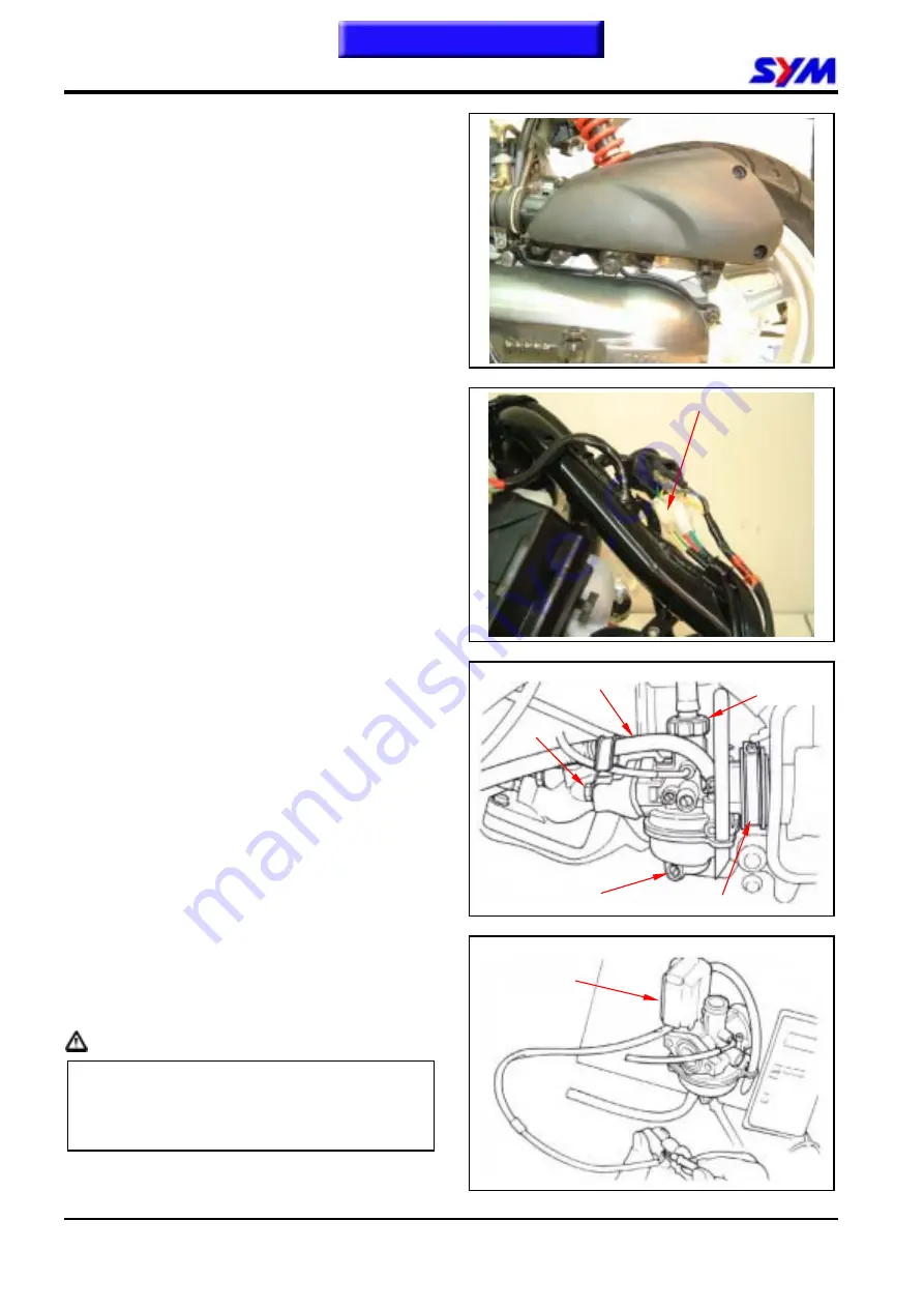
Carburetor Remove
Remove the body cover.
Disconnect the auto by-starter connector.
Loosen draining screw and then drain out fuel
inside the carburetor.
Loosen carburetor upper part and remove
carburetor upper part.
Remove fuel and oil hoses from carburetor.
Remove carburetor mounting bolt and
carburetor.
Auto By-Starter
Inspection
Connect resistor meter to the terminals of auto
by-starter, and then measure its resistance.
If the resistance value exceeds specification too
much, it means that the PTC in the auto
by-starter is malfunction. Then, replace the
auto by-starter.
Resistance value: Max. 10
Ω
(at cold engine)
Caution
If the resistance value exceeds the standard a
little bit, the auto by-starter may still in normal.
However, it is necessary to check other
relative components for damage.
Auto by-starter
Carburetor
upper part
Connection hose clamp
Auto by-starter
Bolt
Fuel hose
Draining screw
Summary of Contents for Euro 100
Page 1: ...SERVICE MANUAL Forward Contents How To Use This Manual Mechanism Illustrations 50 100 50 100...
Page 7: ......
Page 25: ...1 GENERAL INFORMATION 1 18 Note This chapter Contents...
Page 45: ...3 LUBRICATION SYSTEM 3 6 NOTES This chapter Contents...
Page 81: ...8 FINAL DRIVING MECHANISM 8 6 Notes This chapter Contents...
Page 97: ...10 FUEL SYSTEM 10 10 Notes This chapter Contents...
Page 109: ...11 BRAKE SYSTEM 11 12 Notes This chapter Contents...
Page 121: ...12 BODY COVER 12 12 Note This chapter Contents...
Page 157: ...15 ELECTRICAL EQUIPMENT 15 22 Notes This chapter Contents...
Page 158: ...16 ELECTRICAL DIAGRAM 16 1 JET 50 ELECTRICAL DIAGRAM 16 Home page Contents...
Page 159: ...16 ELECTRICAL DIAGRAM 16 2 JET 50 EURO ELECTRICAL DIAGRAM Home page Contents...
Page 160: ...16 ELECTRICAL DIAGRAM 16 3 JET 100 ELECTRICAL DIAGRAM Home page Contents...
Page 161: ...16 ELECTRICAL DIAGRAM 16 4 Notes Home page Contents...


