background image

90 Starting the Network Security console

Launching the console

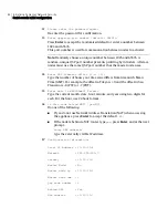
To launch the console on Linux

1

Change to the directory where the console application is installed. For 
example:

cd /usr/SNS_console

2

Type the following command:

java -jar -Xmx256m snsadmin.jar

If the location of the 

java

 program is not in your PATH environment 

variable, you can provide the full path in the command. For example:

/usr/local/bin/java -jar -Xmx256m snsadmin.jar

The option 

-Xmx256m

 allots the required memory for the application.

3

In 

Symantec Network Security

, enter the administration IP address of the 

appliance into the 

Hostname

 text box.

See

“Using the correct administration IP address”

 on page 89.

4

In the 

Port

 text box, enter the qspproxy (QSP) port number for the 

appliance.
The port number is set during initial configuration of the appliance.

5

In the 

Username

 text box, enter 

superuser

The 

superuser

 username is configured by default during initial 

configuration. This account has the highest level of privileges when used to 
log in on the Network Security console.

6

In the 

Passphrase

 text box, enter the superuser passphrase that was set 

during initial configuration.

7

Click 

OK

.

Summary of Contents for 10521148 - Network Security 7161

Page 1: ...Symantec Network Security 7100 Series Implementation Guide...

Page 2: ...re and Symantec Security Response are trademarks of Symantec Corporation Other brands and product names mentioned in this manual may be trademarks or registered trademarks of their respective companie...

Page 3: ...signatures that ensure the highest level of protection Global support from Symantec Security Response experts which is available 24 hours a day 7 days a week worldwide in a variety of languages Advan...

Page 4: ...er Service online go to www symantec com select the appropriate Global Site for your country then choose Service and Support Customer Service is available to assist with the following types of issues...

Page 5: ...his agreement You may not A sublicense rent or lease any portion of the Software reverse engineer decompile disassemble modify translate make any attempt to discover the source code of the Software or...

Page 6: ...D REGARDLESS OF WHETHER ANY REMEDY SET FORTH HEREIN FAILS OF ITS ESSENTIAL PURPOSE IN NO EVENT WILL SYMANTEC OR ITS LICENSORS BE LIABLE TO YOU FOR ANY SPECIAL CONSEQUENTIAL INDIRECT OR SIMILAR DAMAGES...

Page 7: ...ux included with the Appliance All Excluded Software is licensed under the GNU General Public License Version 2 June 1991 a copy of which is included with the user documentation for the Appliance The...

Page 8: ...8...

Page 9: ...ing the 7100 Series components About the 7100 Series components 17 About 7100 Series models 17 Model 7120 18 Model 7160 19 Model 7161 20 About core components 21 LCD panel 22 LED lights 24 Serial port...

Page 10: ...7100 Series 45 Rack mounting 46 Mounting the appliance to a two post rack 46 Mounting the appliance to a four post rack 47 Cabling 49 Cabling for model 7120 49 Connecting the management reset and ser...

Page 11: ...Linux 86 Installing the console 86 Installing the Java Runtime Environment 87 Installing the console on Windows 87 Installing the console on Linux 88 Launching the console 88 Using the correct admini...

Page 12: ...ction and response About detection and response 115 Starting a sensor on an appliance interface 115 About protection policies 116 Creating and applying protection policies 116 Viewing a protection pol...

Page 13: ...sh card 143 Making a non bootable CF card on Windows 143 Making a non bootable CF card on Linux 143 Using the compact flash for backup and restore 144 Using the compact flash for backup 145 Using the...

Page 14: ...ing and unconfiguring About re imaging and unconfiguring 167 Unconfiguring Symantec Network Security 168 Running Unconfigure in the Network Security console 168 Running Unconfig SNS on the LCD 169 Run...

Page 15: ...ng 183 Accessing troubleshooting information 183 Appendix B Specifications and safety Product Specifications 185 Safety guidelines 186 Product certifications 188 Appendix C Service Manual About the re...

Page 16: ...8 Contents...

Page 17: ...nes superior detection and prevention capabilities with flexible deployment options and ease of installation Network Security 7100 Series are highly scalable purpose built appliances that meet a range...

Page 18: ...ion architecture that combines anomaly signature statistical and vulnerability detection techniques into an Intrusion Mitigation Unified Network Engine IMUNE IMUNE proactively prevents and provides im...

Page 19: ...ntrusion detection in a single appliance The 7120 Monitors up to four 10 100 Base T network segments Provides a maximum bandwidth license of 200 Mbps The 7160 Monitors up to eight 10 100 1000 Base T n...

Page 20: ...interfaces including in line pairs and interface groups Chapter 9 Configuring detection and response Describes how to start sensors by configuring and applying protection policies Also describes how...

Page 21: ...ard This card provides the minimum procedures necessary for installing configuring and starting to operate the Symantec Network Security 7100 Series appliance printed and PDF Symantec Network Security...

Page 22: ...mantec com techsupp enterprise select_product_manuals html and click Intrusion Detection Symantec Network Security 4 0 The Knowledge Base provides a constantly updated reference of FAQs and troublesho...

Page 23: ...Ethernet crossover cable for imaging and diagnostics Rack mounting hardware 2 metal L brackets 8 screws for attaching the brackets to the appliance 4 rubber feet For use when installing the appliance...

Page 24: ...16 Introduction Verifying the materials...

Page 25: ...tworking interfaces multi gigahertz CPUs and plenty of memory with a number of convenience features into a fast simple and reliable appliance Additionally the LCD subsystem compact flash removable har...

Page 26: ...power supply 2 Master power switch Switch that turns the appliance on or off 3 DB9 serial port Connection for the serial console cable 4 USB ports Either port can be connected to the USB port of a by...

Page 27: ...ctions for the AC power cords two redundant power supplies including four fans for cooling the appliance interior 2 Power switch Switch that turns the appliance on or off 3 USB ports Either port can b...

Page 28: ...100 1000Base T 12 re1000g6 Monitoring interface 10 100 1000Base T 13 re1000g7 Monitoring interface 10 100 1000Base T 14 eth8 RST0 reset interface for sending TCP resets to malicious or unwanted flows...

Page 29: ...apter Read write drive for compact flash cards of up to 1 GB capacity 6 re1000g0 Monitoring interface also the Imaging Server connection for re imaging the appliance 1000Base SX fiber 7 re1000g1 Monit...

Page 30: ...Compact flash adapter Figure 2 4 shows these components on the front and back panels of a 7160 Figure 2 4 7160 core components LCD panel The LCD panel includes the LCD screen and six push buttons The...

Page 31: ...2 4 LCD panel components Diagram location Component name Description 1 LCD screen Provides a backlit 2 line by 16 character display 2 Left arrow button Scrolls through menu choices and moves the curso...

Page 32: ...4 See Restarting rebooting and powering off on page 148 See Unconfiguring Symantec Network Security on page 168 Using the Network Security console you can lock the LCD panel to prevent unauthorized ac...

Page 33: ...Preparing for re imaging on page 170 Use the serial console to access the appliance operating system or Symantec Network Security software for troubleshooting See Using the serial console on page 158...

Page 34: ...onfiguration information Upgrading to a major new version of Symantec Network Security Upgrading to a major new version of the operating system Booting from compact flash during appliance re imaging o...

Page 35: ...llout panel on the bottom of the appliance If you should ever need to ship your appliance to Symantec for support this provides a convenient method of extracting the drive before shipping the applianc...

Page 36: ...es ideally connect to separate power sources Each of the redundant power supplies has two internal power main connections In the event of a failure of one power main the other one continues to provide...

Page 37: ...locking interface grouping fail open clustering high availability and in combination with third party IDS products The Symantec Network Security 7100 Series provides the flexibility to meet the needs...

Page 38: ...ation about licensing see Licensing on page 91 Passive mode Passive mode is the default method of monitoring traffic on network segments It provides intrusion detection with logging alerting and respo...

Page 39: ...ting scripts or programs traffic recording and more Blocking Prevents malicious traffic from entering your network Also provides the same configurable alerts and responses offered in alerting mode Bot...

Page 40: ...signated for in line pair 0 and pair 1 on the 7120 Figure 3 1 In line pairs on the 7120 Figure 3 2 shows the interfaces designated for in line pairs 0 1 2 and 3 on the 7160 and 7161 Figure 3 2 In line...

Page 41: ...tration Guide Deployment using in line mode The initial setup for in line mode requires an interruption to network traffic while you make the necessary cabling changes The appliance must be physically...

Page 42: ...ngle interface Any policy you create for an interface group applies to all interfaces in the group Interfaces that are part of a group cannot be configured individually An interface group can only inc...

Page 43: ...anel LEDs on the bypass unit About the In line Bypass unit Since in line mode by definition places the appliance into the network path a hardware or software failure affecting the interface pair will...

Page 44: ...s unit models operate at wire speeds and have no impact on performance The 2 In line Bypass unit You can deploy the 2 In line Bypass unit with a 7120 Figure 3 4 shows the rear panel of the 2 In line B...

Page 45: ...port of each port group is implemented as 10 100 1000Base T MDI Consult the documentation for your network devices to determine whether they require crossover connections You must supply at least four...

Page 46: ...line mode If the appliance has a hardware or software failure fail open is activated when the bypass unit senses the failure via the USB connection and switches to bypass mode Link parameters on bypas...

Page 47: ...arameters by clicking each interface object in the in line pair See Interface status parameters on page 133 The parameter values for all interfaces in the port group should be the same when the bypass...

Page 48: ...ws when port group 1 is operating in online mode 2 P2 Port group 2 The P2 LED glows when port group 2 is operating in online mode 3 P3 Port group 3 The P3 LED glows when port group 3 is operating in o...

Page 49: ...y Administration Guide Table 3 5 Bypass unit rear panel LED descriptions LED label LED name Description LT Link test The LT LED glows green to indicate an active link signal on the port ALM Alarm The...

Page 50: ...ation Guide Network Security console accessibility The Network Security console is a Java application that runs on a separate computer You can deploy the console on any computer that can access the 71...

Page 51: ...pdates to single nodes or node clusters schedule automatic updates view current and applied versions and keep your systems updated to the latest levels You can configure the 7100 Series for automatic...

Page 52: ...44 Deploying the 7100 Series Symantec LiveUpdate accessibility...

Page 53: ...t you want to protect The appliance can be mounted facing either direction in your rack so consider which side will have access to the ports and compact flash and which will have access to the LCD pan...

Page 54: ...o mount the brackets at the rear of the appliance Alternatively you can use other mounting hardware to attach the appliance to your rack such as sliding rails or a shelf Warning Installing the applian...

Page 55: ...bracket in the same way to the opposite side of the appliance 4 With assistance lift the appliance into place so that the short flanges of the L brackets are pressed against the rack posts 5 Using th...

Page 56: ...iance 2 Attach the bracket by inserting four of the provided screws through the slots in the bracket into the holes in the appliance casing Tighten the screws completely 3 Attach the other L bracket i...

Page 57: ...propriate section See Cabling for model 7160 on page 54 See Cabling for model 7161 on page 62 The following topics are covered here Connecting the management reset and serial ports Cabling for passive...

Page 58: ...a faster bus than port 3 which may be a consideration depending on how busy your network segments are All ports are 10 100 Base T Ethernet ports To cable the 7120 for passive mode monitoring Connect...

Page 59: ...provide fail open capability The 2 In line Bypass unit is recommended for operation with the 7120 appliance Note Only the 2 In line Bypass unit is supported for use with model 7120 Figure 4 3 shows th...

Page 60: ...ppliance to port group 0 on the bypass unit Connect in line pair 1 on the 7120 to port group 1 on the bypass unit The Net A port of each port group on the bypass unit is implemented as 10 100 1000Base...

Page 61: ...a sensor on the in line pair that is connected to that port group Event detection can occur only when the port group is in online mode See Starting a sensor on an appliance interface on page 115 To ca...

Page 62: ...g the 7120 off before initial configuration If you need to power the 7120 off before performing initial configuration you can use the master power switch or the Shutdown Host option on the LCD After i...

Page 63: ...gure 4 5 7160 back panel Connecting the management reset and serial ports You need four Ethernet cables of an appropriate length to connect the management and reset ports to your network Use the provi...

Page 64: ...er or a switch To cable the 7160 for passive mode monitoring Connect ports 0 through 7 of the appliance to the eight network segments that you want to monitor Cabling for in line mode monitoring The 7...

Page 65: ...pliance to one side of network segment 3 6 Connect port 5 of the appliance to the other side of network segment 3 7 Connect port 6 of the appliance to one side of network segment 4 8 Connect port 7 of...

Page 66: ...nit contains four port groups each with four ports Two ports Net A and App A are associated with one port of the 7160 in line pair and the corresponding side of the network The other two ports in the...

Page 67: ...160 0 Port 0 1 Port 1 2 Port 2 3 Port 3 4 Port 4 5 Port 5 6 Port 6 7 Port 7 8 RST0 9 RST1 10 RST 2 11 Management port 12 Mgmt USB on bypass unit 13 USB ports 14 In line pair 0 15 In line pair 1 16 In...

Page 68: ...Do not force the link speed or duplex mode to a specific setting on network devices that connect to Net A or Net B See About the In line Bypass unit on page 35 To connect the bypass unit App A and Ap...

Page 69: ...network 3 Connect App A of port group 2 to port 4 on your appliance 4 Connect App B of port group 2 to port 5 on your appliance 5 On the bypass unit connect Net B of port group 2 to the other side of...

Page 70: ...The 7160 powers up automatically and the alarm will sound 3 Plug the second power cord into a different AC power source Powering the 7160 off before initial configuration If you need to power the 716...

Page 71: ...ou connect only one power cord Figure 4 9 shows the back panel of the 7161 Figure 4 9 7161 back panel Connecting the management reset and serial ports You need four Ethernet cables of an appropriate l...

Page 72: ...ltimode fiber cables with LC fiber optic connectors for the 7161 fiber ports and Ethernet cables with RJ45 connectors for the copper ports To access network segments for monitoring you can connect eac...

Page 73: ...her side of network segment 1 3 Connect port 2 of the appliance to one side of network segment 2 4 Connect port 3 of the appliance to the other side of network segment 2 5 Connect port 4 of the applia...

Page 74: ...e of the power cords into an AC power source The 7161 powers up automatically and the alarm will sound 3 Plug the second power cord into a different AC power source To power the 7161 on after the init...

Page 75: ...s you for information after which Symantec Network Security is installed on the 7100 Series node Some of the required information depends on whether you are adding the appliance as a master or a slave...

Page 76: ...plays a menu with the three configuration method choices and a fourth menu item for shutting down the appliance After a minute or so of inactivity the LCD reverts to displaying the date and time You c...

Page 77: ...of a master node by using the LCD panel To configure your appliance as a slave node see Using the LCD panel to configure a slave node on page 72 To use the LCD panel for initial configuration of a ma...

Page 78: ...P Netmask 000 000 000 000 use the arrow buttons to enter the netmask for the local subnet for example 255 255 255 000 The netmask designates the part of the address that refers to the network as oppos...

Page 79: ...th date hour minute and year using two digits for each Use 24 hour format for the hour For example May 12 2004 at 1 05pm is entered as 0512130504 Press e 10 For Superuser Pswd a use the arrow buttons...

Page 80: ...NS Yes No do one of the following To proceed with installation of Symantec Network Security leave the cursor on Yes To start the initial configuration process over use the arrow buttons to move the cu...

Page 81: ...em is not displayed press any button to return to the menu or press the up or down arrow buttons to scroll through the menu 3 For Local IP Address 000 000 000 000 use the arrow buttons to enter the lo...

Page 82: ...ique node number Press e Note The node number must match the number you provide when adding the slave node object to the topology tree in the Network Security console You can assign a unique number be...

Page 83: ...e password for unlocking the LCD matches the secadm password You can select lower and upper case letters numbers and a subset of special characters 11 For QSP Port Number 6234 5 use the arrow buttons...

Page 84: ...ess 000 000 000 000 use the arrow buttons to enter the externally visible IP address Press e 15 For Configure SNS Yes No do one of the following To proceed with installation of Symantec Network Securi...

Page 85: ...configuration Starting a serial console Before you can begin the configuration you must connect the appliance to the serial terminal device and start the serial terminal application To start the seria...

Page 86: ...k designates the part of the address that refers to the network as opposed to the host A typical netmask is 255 255 255 0 6 Enter the gateway address for this node Type the gateway IP address This is...

Page 87: ...ou can change the passwords for root elevate and secadm LCD unlocking after initial configuration You can also change the password for the Network Security console superuser account 12 Please enter th...

Page 88: ...iguring a slave node using the serial console This section contains the procedure for initial configuration of a slave node by using the serial console To configure your appliance as a master node see...

Page 89: ...nnot be changed once you have finished this procedure and installed Symantec Network Security 9 Enter the master node number default 1 Press Enter to accept the default or enter the node number of the...

Page 90: ...ours your time zone differs from Greenwich Mean Time GMT For example the offset in Tokyo is 9 and the offset in San Francisco is 8 PST or 7 PDT 15 Enter date in MMDDhhmmYY format Type the current mont...

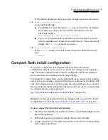
Page 91: ...se it to configure your appliance This convenient method provides a known configuration for a new appliance slave node that you are adding to an existing topology To prepare the compact flash use the...

Page 92: ...count will become the new password for unlocking the LCD panel either from the panel itself or from the Network Security console Under normal operation all tasks can be completed from the Network Secu...

Page 93: ...next step is to install the Network Security console on a separate machine The Network Security console is a Java application that will run on a Windows or Linux machine You can use the console to pe...

Page 94: ...s included with your appliance You can install it on a Windows or Linux machine that has the correct version of the Java Runtime Environment Table 6 1 Console requirements on a Windows system Paramete...

Page 95: ...all the JRE for you Installing the console on Windows This section describes how to install the console on a Windows machine You should close all other programs before running the console installer To...

Page 96: ...Linux machine To install the console on Linux 1 Insert the Management Console CD into the CD drive of the console system 2 Login as root to the console system 3 Mount the CD filesystem by entering th...

Page 97: ...the console on Windows This section describes how to launch the console on a Windows machine To launch the console on Windows 1 Double click the shortcut to Symantec Network Security on your desktop...

Page 98: ...ory for the application 3 In Symantec Network Security enter the administration IP address of the appliance into the Hostname text box See Using the correct administration IP address on page 89 4 In t...

Page 99: ...ng window prompts you to supply the license file To license a slave node you must connect to the master node and use the menu to access licensing When a license expires a new license must be installed...

Page 100: ...equirement estimate is too low Additive licenses provide additional bandwidth for your license Table 7 2 shows the available additive licenses Installing licenses The Symantec Network Security softwar...

Page 101: ...ster node using the Network Security console the License Information window appears When you add a slave node you can access licensing by first connecting to the master node with the Network Security...

Page 102: ...er is also known as the license serial number The Appliance Serial Number This serial number is found on the back panel label on the 7100 Series appliance itself It includes the letters FLX followed b...

Page 103: ...a serial console on page 77 2 Login as secadm 3 To become root type elevate and enter the node password or the specific root password if the appliance has one 4 Type the following command usr SNS tool...

Page 104: ...y console You can rename the file with a descriptive name 2 Log in to the Network Security console with the superuser account 3 In License Information do one of the following Click Browse to navigate...

Page 105: ...t licensing on page 91 To check the license status 1 On Devices click the 7100 Series node for which you wish to retrieve licensing information 2 In the right pane in the License Status table review t...

Page 106: ...f you underestimate your bandwidth you can request an additive license See Table 7 2 Additive licenses on page 92 Caution If the excess traffic continues the Symantec Network Security software may shu...

Page 107: ...Security console To install the additive license file 1 Save the license file to the computer where you installed the Network Security console If you wish rename the file with a descriptive name 2 Lo...

Page 108: ...tificate See Determining the serial numbers on page 94 Appliance Serial Number The serial number printed on a label on the back panel of the appliance See Determining the serial numbers on page 94 Sym...

Page 109: ...presenting 7100 Series nodes Network Security software nodes monitoring interfaces routers network segments and other aspects of the network The topology database is established during the initial ins...

Page 110: ...ndependent single node or as a slave node in a cluster A slave node is synchronized with a master node within a cluster or group of Network Security nodes A single node behaves like a master node in a...

Page 111: ...dress of the node It is used for synchronization and communication between the master and slave nodes On a master node it is also used to connect to the Network Security console This is a required fie...

Page 112: ...status If the current master node fails another node in the group takes over as the functioning master See the Symantec Network Security Administration Guide for more information Master Node Sync Inf...

Page 113: ...dd or edit a 7100 Series node 1 On the Devices tab do one of the following To add a node right click Symantec Network Security Nodes and select Add Node 7100 Series Node Select A Model Click the model...

Page 114: ...r and enter a Failover Group Number between 1 and 99 inclusive All nodes within the failover group must use the same group number 8 Do one of the following If adding a 7100 Series node in a cluster in...

Page 115: ...e allowing the interface to process network traffic You may also want to update other interface fields About monitoring interface fields There are a number of fields to fill in when you edit an interf...

Page 116: ...et Interface click the reset interface in the pull down list The selected reset interface must be cabled to access the monitored network See Cabling on page 49 6 In Description optionally enter descri...

Page 117: ...entered a descriptive name for the interface it is displayed in the topology tree in place of the standard interface name The other changes you made are displayed in the right pane of the Network Sec...

Page 118: ...tion Name A descriptive name for the in line pair of up to 40 characters This is the object name displayed in the topology tree Expected Throughput The amount of network traffic you expect this in lin...

Page 119: ...e 7100 Series node object and click Add In line Pair in the pop up menu Right click on an existing in line pair object and click Edit in the pop up menu 2 In Add In line Pair or Edit In line Pair ente...

Page 120: ...r object is displayed in the topology tree with the two designated interfaces listed below it Configuring an interface group If your network utilizes asymmetric routing an interface group is an effect...

Page 121: ...n existing interface group object and click Edit in the pop up menu 2 In Add Interface Group or Edit Interface Group enter a descriptive name Expected Throughput The amount of network traffic you expe...

Page 122: ...other networks protected by this interface Enter the network IP addresses in CIDR format Caution You must replace the default entry 0 0 0 0 0 in the Networks tab with valid monitored networks in CIDR...

Page 123: ...pair or interface group The detected events are handled according to policies that you apply You can also create and apply response rules for specific event types and source or destination addresses R...

Page 124: ...directly or clone and customize to suit your needs You can apply a policy to one or more interfaces but an interface can have only one policy applied to it at a time If you apply a new policy to an i...

Page 125: ...policy Setting policies to interfaces Unapplying or removing policies from interfaces Enabling disabling blocking on in line pairs Adding a new protection policy Cloning existing protection policies...

Page 126: ...otection Policies tab click a protection policy in the left pane 2 Click Set to Interfaces 3 In Apply Policy to Selected Interface check one or more interfaces in line pairs or interface groups to app...

Page 127: ...the following Click Disable Blocking Click Enable Blocking 3 Click Apply Adding a new protection policy When adding a new policy you select the events to be logged or blocked To add a new protection p...

Page 128: ...olicy 2 Click Edit 3 On Search Events in Search Parameters you can input search criteria to shorten the displayed list of event types See Using Search Events on page 120 4 In the Search Events tab or...

Page 129: ...l down list In Confidence set a confidence level from the pull down list In Intent select an intention from the pull down list In Blocked select whether you want to see events with blocking enabled or...

Page 130: ...ection Policies tab do one of the following Click New Click Edit 2 In Add Protection Policy do one of the following Click Search Events Click Full Event List 3 To select the events to log or block do...

Page 131: ...ask in CIDR format 12 In Destination Port enter the port number 13 In IP Range List you can enter a range of IP addresses rather than entering them one at a time in Source and Destination 14 Do one of...

Page 132: ...e mode on the 7100 Series Response rules have no effect on sensor behavior Configurable responses include Console notification Email or pager notification SNMP trap Traffic recording TCP reset TrackBa...

Page 133: ...interfaces to which the response rule will apply and click OK 5 Click the Event Type cell of the response rule 6 In Select Events select the attack types to which the response rule applies and click...

Page 134: ...leting response rules This section describes how to delete a response rule To delete a response rule 1 In the Network Security console click Configuration Response Rules 2 In Response Rules select the...

Page 135: ...similar or related events and creates an incident named after the event with the highest priority Incidents are displayed in the Network Security console on the Devices tab when you click an interfac...

Page 136: ...incident You can display incident or event details to drill down for more information Viewing incident data The Incidents tab provides a view of top level incident data To view incident data In the Ne...

Page 137: ...nt right click an event row 3 Click View Event Details from the pop up list 4 View the information 5 Click Close Managing incident data You can mark annotate email copy and paste save and print incide...

Page 138: ...nt the report 8 Click File Close to close the report For detailed information about report types and report scheduling see the Symantec Network Security Administration Guide Monitoring appliance statu...

Page 139: ...liance health statistics Screens with example values are Hostname sns7161 1 This is the hostname of the appliance a default is shown IP Address 10 127 9 216 This is the IP address of the appliance App...

Page 140: ...ck the interface object the status display in the right pane includes a column for each sensor process and a column for the aggregate values Some but not all parameters have values for each sensor pro...

Page 141: ...erage Bandwidth The bandwidth averaged over the last statistics interval Current Versions Network Security Version The version of Symantec Network Security on the node Security Update The Security Upd...

Page 142: ...e interface in megabits per second Link Duplex Full or half duplex Table 10 3 In line pair status parameters Parameter Explanation Packet Statistics Receive Bit Rate bps The bits per second currently...

Page 143: ...ecurity events per second seen on the in line pair Displayed for each sensor process Flow Statistics New TCP Flows Second The number of new TCP flows per second on the in line pair Displayed for each...

Page 144: ...played for each sensor process Average Packet Size bytes The packet size in bytes averaged over the last statistics interval Distribution of Packets Received The percentage of total packets received o...

Page 145: ...appliance Maintenance and administration on the Symantec Network Security 7100 Series is essential for managing the appliance and its software This includes making backups restarting software and har...

Page 146: ...iles with SCP You can configure Symantec Network Security to transfer log files to another computer when the files reach a certain size The 7100 Series uses SCP to securely copy the files across the n...

Page 147: ...automatic log rotation to the target host To configure automatic log rotation 1 Do one of the following On Devices right click the 7100 Series node object then click Configuration Network Security Par...

Page 148: ...e or to the compact flash Backup files are saved in tar format When restoring files you can choose from saved files on both the hard drive and compact flash Periodic backups of the Symantec Network Se...

Page 149: ...rogress bar closes click Close to exit Restoring a configuration You can restore a configuration to the same node or to a different similar node Symantec Network Security must be running when you rest...

Page 150: ...onfiguration changes that were made since the backup About the compact flash All models of the Symantec Network Security 7100 Series have a compact flash CF adapter located on the back panel The CF ad...

Page 151: ...To make a non bootable CF card on Windows 2000 or XP 1 Insert a new CF card into the USB CF adapter 2 Click Start Run 3 In Run in the Open textbox type diskmgmt msc 4 Right click the drive letter that...

Page 152: ...tting to non bootable 16 To select partition 1 as the non bootable partition type 1 17 To write the configuration to the CF and quit fdisk type w 18 At the shell prompt to format the partition type mk...

Page 153: ...r the backup 7 Click OK Network Security adds a timestamp to the filename to ensure uniqueness 8 When the progress bar closes click Refresh Table to view the backup Using the compact flash for restore...

Page 154: ...ation This provides a way to control the configuration of one or more appliances you are adding to a cluster Before physically installing a new slave appliance use the Network Security console to add...

Page 155: ...uter will automatically update after the slave appliance is connected to the network and initially configured These values will appear on the Advanced Network Options tab when you edit the node 7 Opti...

Page 156: ...tarting rebooting and powering off The 7100 Series provides multiple methods of starting restarting or stopping Symantec Network Security rebooting the operating system and powering down the appliance...

Page 157: ...op Symantec Network Security from the LCD 1 On the appliance front panel press any button to change the LCD display If the LCD screen is locked see Unlocking the LCD panel on page 155 to unlock it 2 P...

Page 158: ...depending on the model 4 Press e to start Symantec Network Security Starting Network Security from the serial console This section describes the procedures for using the serial console to start the Ne...

Page 159: ...oting the appliance You can reboot the appliance from the Network Security console LCD panel or serial console See the following sections for information Rebooting the appliance from the Network Secur...

Page 160: ...e procedure for rebooting the appliance on the serial console To reboot the appliance from the serial console 1 Connect your laptop or other serial device to the appliance with the serial console cabl...

Page 161: ...see SNS7120 5 Shutdown Host where 7120 is replaced by 7160 or 7161 depending on the model 4 Press e to shut down and power off the appliance Powering off the appliance from the serial console This se...

Page 162: ...e appliance You must reboot the appliance before the change takes effect Also exit your Network Security console and restart it using the new IP address See Changing the IP address on page 156 3 Stop...

Page 163: ...See Unlocking the LCD panel on page 155 3 When you see the first menu item SNS7120 1 Lock LCD press the down arrow button to scroll down through the menu choices 4 When you see the command you want to...

Page 164: ...ght pane do one of the following Click True to enable LCD panel locking Click False to disable LCD panel locking 5 Click Apply 6 In Apply Changes To check the node on which to enable or disable LCD lo...

Page 165: ...to move the cursor brackets 5 For IP Netmask 000 000 000 000 use the arrow buttons to enter the netmask for the new subnet for example 255 255 255 000 Press e 6 For IP Gateway 000 000 000 000 use the...

Page 166: ...opping and starting the software or appliance or other administrative tasks You can connect the provided serial console cable from the appliance to any serial enabled device and log in using a serial...

Page 167: ...riginal unconfigured setting The appliance is then ready for initial configuration See Running unconfigure on the serial console on page 170 install bridge Runs the installation procedure for the Syma...

Page 168: ...change the root password from the serial console Changing the root password also changes the password for the elevate command These passwords are always the same To change the root password from the...

Page 169: ...in order to prepare for using SESA Preparing to use SESA To use SESA with Symantec Network Security you must do two things in preparation Make sure that the appliance host name can be resolved Make t...

Page 170: ...twork Security SIP file is available on the Management Console CD You can access it directly from the CD or copy it to any location on the SESA manager When you run the SESA integration wizard on the...

Page 171: ...and log in as secadm See Starting a serial console on page 77 2 At the SNS7100 prompt type install bridge 3 The system warns you about stopping Symantec Network Security To install the SESA Bridge Sym...

Page 172: ...d SESA agent Symantec Network Security must be stopped and restarted To uninstall the SESA bridge 1 At the SNS7100 prompt type uninstall bridge 2 The system warns you about stopping Symantec Network S...

Page 173: ...arting a serial console on page 77 2 On the serial console at the SNS7100 prompt type elevate and enter the root password 3 At the shell prompt type cd opt Symantec sesa and press Enter 4 Type agentd...

Page 174: ...166 Maintaining and administering the 7100 Series Using the serial console...

Page 175: ...g operating system intact but removes the Symantec Network Security installation and configuration Re imaging the Symantec Network Security 7100 Series appliance involves reinstalling operating system...

Page 176: ...rds and node number The node object is removed from the topology in the Network Security console The 7100 Series is ready for initial configuration after unconfiguring Symantec Network Security There...

Page 177: ...n page 67 Running Unconfig SNS on the LCD The Unconfig SNS command is available on the LCD run menu To run Unconfig SNS on the LCD run menu 1 Press any button to display the LCD run menu 2 If the LCD...

Page 178: ...o restore it after imaging You can use the 7100 Series serial console to create a bootable CF card or you can create one on the Imaging Server if it has a CF adapter The following sections provide mor...

Page 179: ...appliance on Creating a bootable compact flash via the serial console You can use the serial console on the 7100 Series to create a bootable compact flash See Starting a serial console on page 77 To c...

Page 180: ...connected to the USB port on the Imaging Server The USB CF adapter must be fully functional on the computer even before the software is installed from the Recovery Software CD The USB driver is not pr...

Page 181: ...Server on a RedHat Linux system by installing the software packages on the Recovery Software CD This involves more steps but works with a wider range of hardware See the following sections Setting up...

Page 182: ...ing Server 3 Reboot the Imaging Server Wait while the Imaging Server boots from the Recovery Software CD 4 When the Symantec Network Security Appliance License and Warranty Agreement is displayed read...

Page 183: ...ning The Imaging Server must be configured as a DHCP server for the private network which includes the appliance s during the imaging process Therefore it cannot be connected to a network that has ano...

Page 184: ...xinetd and nfs services that will be needed during imaging 11 The script copies all files from mnt cdrom home bto into the home bto directory on the Imaging Server The Imaging Server is now ready to i...

Page 185: ...d regular Ethernet cable from the left most RJ45 port port 0 on the 7120 to the hub or switch Note If you use a switch configure it so that the two ports can pass network traffic between them 3 Confir...

Page 186: ...nto a media converter 3 Plug the media converter into port 0 on the 7161 This is the left most top fiber port as viewed from the back 4 Confirm that the link light is lit for port 0 on the 7161 and on...

Page 187: ...t off gracefully before beginning the re imaging or upgrading process You can do this from the LCD panel or serial console See Powering off the appliance on page 152 5 Insert the bootable compact flas...

Page 188: ...then displays Installing SNS then Rebooting System As the appliance is booting the LCD displays Symantec v1 03 Diagnostics When it is fully booted and ready for initial configuration the LCD displays...

Page 189: ...package you can install it on your system If your console system is running Windows run the console installer executable by double clicking it See the Readme file provided with the upgrade package fo...

Page 190: ...182 Re imaging and unconfiguring About migration...

Page 191: ...ation Use the following procedure to access troubleshooting information from the Symantec Knowledge Base To access Symantec Network Security 7100 Series troubleshooting information 1 Go to www symante...

Page 192: ...184 Troubleshooting Accessing troubleshooting information On the Browse tab expand a category to see a list of knowledge base articles related to that topic Click an article to view it...

Page 193: ...specifications Parameter 7120 7160 7161 Length 43 18 cm 17 in 61 cm 24 in 61 cm 24 in Width 43 18 cm 17 in 43 18 cm 17 in 43 18 cm 17 in Height 5 08 cm 2 in 8 89 cm 3 5 in 8 89 cm 3 5 in Weight 8 62...

Page 194: ...re unless proper ventilation is provided Environmental operating temperature range 5 to 35 C 41 to 95 F 5 to 40 C 41 to 104 F 5 to 40 C 41 to 104 F Storage temperature range 10 to 70 C 14 to 158 F 20...

Page 195: ...ver will void your warranty Warning To prevent a possible electrical shock when installing the 7100 Series unplug the power cord before installing network cables Warning To prevent a possible electric...

Page 196: ...ing Electrical Business Equipment UL 60950 3rd Edition and CAN CSA C22 2 No 60950 00 This Class A digital apparatus complies with Canadian ICES 003 VCCI CE FCC part 15B Class A This device complies wi...

Page 197: ...ications EN61000 4 4 1995 EFT Burst 1kV Power 0 5 kV Signal Cables EN61000 4 5 1995 Surge 1kV L L 2 kV L G EN61000 4 6 1996 Conducted RF Immunity 3V 150 kHz 80 MHz EN61000 4 11 1994 95 0 5T 30 25T 95...

Page 198: ...190 Specifications and safety Product certifications...

Page 199: ...hard drive This service manual provides instructions for removing the hard drive from the Symantec Network Security 7100 Series appliance models 7160 and 7161 The 7160 and 7161 have a hard drive that...

Page 200: ...new or repaired 7100 Series appliance Removing the hard drive You can remove the hard drive while the appliance is installed in a rack or you can take the appliance out of the rack for easier access R...

Page 201: ...nd turn it upside down 5 Using a Phillips screwdriver loosen the four screws on the pullout panel 6 Pull the panel away from the appliance It remains attached to the appliance interior with a safety s...

Page 202: ...osen the four screws that are holding the hard drive in place Be sure to leave the metal plate attached to the inside of the pullout panel 10 Carefully slide the hard drive out of the appliance 11 Rea...

Page 203: ...width 98 node 105 node options 103 protection policy 119 response rule 124 slave node 74 75 81 83 administration IP address 89 advanced network options 104 106 147 alarm 62 66 power supply 28 55 63 al...

Page 204: ...modes 38 online mode 38 port groups 37 51 58 rear LEDs 40 USB port 37 In line Bypass unit See bypass unit C cables included with appliance 15 cabling 7120 49 7120 in line mode 50 7160 54 7160 in line...

Page 205: ...logy 101 synchronization 104 default gateway 70 mode for interfaces 30 deleting custom policies 123 interfaces 105 IP address from logging criteria 123 predefined policies 116 response rule 126 sample...

Page 206: ...e 38 failover group 104 failure and bypass mode 38 and fail open 35 causes alarm 28 power supply 28 temperature related 25 fiber interfaces on 7161 20 forcing link parameters 38 fulfillment ID 99 133...

Page 207: ...atus 134 installation about 45 in four post rack 47 in two post rack 46 power 54 62 66 rack mounting 46 installation See also cabling interface about 106 adding 108 editing 108 high bandwidth on 132 i...

Page 208: ...le on 89 making non bootable CF on 143 LiveUpdate 11 43 local IP address compared to NAT address 89 initial configuration 70 73 78 81 log automatic rotation 139 SSH keys 138 logging in policy 116 in l...

Page 209: ...agement 42 88 monitored 108 109 NAT 71 private for imaging 175 segments passive monitoring 30 SESA 42 topology 101 traffic in bypass unit 38 traffic rate 98 Network Security console about 10 85 connec...

Page 210: ...ode 31 performance 30 password change 71 changing 159 changing elevate 160 changing root 160 changing secadm 161 default 68 elevate 159 entering on LCD 71 erase all 168 for serial console 76 in config...

Page 211: ...e system 85 reset port cabling 50 55 63 response rules about 124 adding 124 deleting 126 restarting Network Security from Network Security console 150 from serial console 151 restore cluster 141 from...

Page 212: ...tes See SU slave node 41 changing IP 103 156 edit object for 102 installing license on 96 number 103 restore 141 to license 91 Smart Agent 11 42 specifications product 185 speed on bypass unit 38 SSH...

Page 213: ...ial console 170 unlocking changing LCD password 161 common password 160 disable locking of LCD 156 LCD panel 155 update See LiveUpdate upgrading appliance 167 console 181 USB connecting to bypass unit...

Page 214: ...12 Index...

Reviews: