background image

Lifting heavy objects

Only trained and qualified personnel are allowed to lift heavy objects. The following
precautions need to be taken when you lift heavy objects:

Do not stand or come in the way or walk under when heavy objects are lifted.

Check whether the required tools are complete and intact.

Ensure that the lifting tools are firmly fixed on a wall or fixtures with enough
load-bearing capacity.

If a rope is used, ensure that the angle between two sides of the rope is no
larger than 90°.

Use simple and clear commands while speaking to personnel. This approach
helps to avoid any confusion that can cause accidents and damage to personnel
or materials.

Binding signal cables

Signal cables must be separately bundled from the strong-current cables and
high-voltage cables at a spacing of at least 30 mm.

See

“Overview”

on page 25.

33

Safety guidelines

Lifting heavy objects

Summary of Contents for NetBackup 5230

Page 1: ...Symantec NetBackup Appliance and Symantec Storage Shelf Safety and Maintenance Guide Release 2 6 0 3 NetBackup 5230 ...

Page 2: ...bution and decompilation reverse engineering No part of this document may be reproduced in any form by any means without prior written authorization of Symantec Corporation and its licensors if any THE DOCUMENTATION IS PROVIDED AS IS AND ALL EXPRESS OR IMPLIED CONDITIONS REPRESENTATIONS AND WARRANTIES INCLUDING ANY IMPLIED WARRANTY OF MERCHANTABILITY FITNESS FOR A PARTICULAR PURPOSE OR NON INFRING...

Page 3: ...Symantec Corporation 350 Ellis Street Mountain View CA 94043 http www symantec com Printed in the United States of America 10 9 8 7 6 5 4 3 2 1 ...

Page 4: ...formation Upgrade assurance that delivers software upgrades Global support purchased on a regional business hours or 24 hours a day 7 days a week basis Premium service offerings that include Account Management Services For information about Symantec s support offerings you can visit our website at the following URL www symantec com business support All support services will be delivered in accorda...

Page 5: ... Customer service Customer service information is available at the following URL www symantec com business support Customer Service is available to assist with non technical questions such as the following types of issues Questions regarding product licensing or serialization Product registration updates such as address or name changes General product information features language availability loc...

Page 6: ...existing support agreement please contact the support agreement administration team for your region as follows customercare_apac symantec com Asia Pacific and Japan semea symantec com Europe Middle East and Africa supportsolutions symantec com North America and Latin America ...

Page 7: ...s 17 Appliance Ethernet port LEDs 18 8Gb FC HBA LEDs 19 10GE add in card LEDs 20 Symantec Storage Shelf disk drive module and system LEDs 20 Symantec Storage Shelf I O module and power module LEDs 22 Chapter 3 Safety guidelines 25 Overview 25 Symbol conventions 26 Identifier conventions 26 General power instructions 28 High voltage precautions 28 ESD Electrostatic Discharge 29 Combustible gas 30 B...

Page 8: ...idelines 46 Power and electrical warnings 47 Power safety 48 Power cord usage 48 Power cord criteria 49 AC power connections 49 Checking the resistance and voltage 51 Electrostatic discharge ESD 52 Appliance shutdown and hardware access warnings 53 Front and rear panels 53 Bezel 54 Battery replacement 54 Cooling and airflow 55 Laser peripherals or devices 55 Chapter 6 Troubleshooting 57 Troublesho...

Page 9: ...pliance 63 Product EMC Compliance Class A Compliance 64 Product ecology compliance 65 Certifications Registrations Declarations 65 Electromagnetic compatibility notices 66 FCC Verification Statement USA 66 ICES 003 Canada 67 CE Declaration of Conformity Europe 67 VCCI Japan 67 BSMI Taiwan 67 Index 68 9 Contents ...

Page 10: ...ures of the NetBackup 5230 appliance The disks in Slots 0 and 1 provide the operating system for the appliance The NetBackup 5230 appliance contains eight data storage disks in slots 4 through 11 Disks that have 1 TB formatted storage capacity provide a RAID6 group and 4 TB of storage You can also use 3 TB disks for 14 TB of storage The following image shows the storage disks circled in yellow The...

Page 11: ...erial port reserved 3 USB ports quantity 3 4 Remote management port 5 10Gb Ethernet ports labeled from left to right eth4 NIC5 and eth5 NIC6 6 See Appliance dimensions and weight on page 13 FTMS support The NetBackup 5230 Appliance supports some Fibre Transport media server FTMS configurations Some NetBackup 5230 Appliance configurations do not support FTMS You need to understand the difference be...

Page 12: ...wing images and tables show the D and the E configurations Figure 1 1 NetBackup 5230 Appliance configuration D Table 1 2 NetBackup 5230 Appliance configuration D components Component Number Target ports on FC cards 1 Initiator ports on FC cards 2 SAS RAID ports 3 10 Gb Ethernet ports 4 Figure 1 2 NetBackup 5230 Appliance configuration E Table 1 3 NetBackup 5230 Appliance configuration E components...

Page 13: ... Shelf dimensions and weight on page 15 Symantec Storage Shelf description The NetBackup 52xx appliance can be ordered with 0 1 2 3 or 4 storage shelves The appliance provides 4 TB of storage capacity without any storage shelves The front and the rear panels of the storage shelf are shown in the following images The following table describes the components of the front panel Table 1 4 Front panel ...

Page 14: ... the components of the rear panel Table 1 5 Rear panel components Description Number Serial port not to be used without Symantec approval 1 I O module release latch 2 I O module 1 3 SAS_IN port 4 SAS_OUT port 5 I O module 2 6 Power supply and fans 1 7 Power supply and fans 2 8 See Symantec Storage Shelf dimensions and weight on page 15 14 Product overview Symantec Storage Shelf description ...

Page 15: ...lf Provides the compliance and environmental information Symantec NetBackup 5230 Product Description Guide Describes the hardware installation and startup procedures for the appliance and the storage shelf The document includes hardware validation and initial configuration instruction Symantec NetBackup 52xx Hardware Installation and Initial Configuration Guide You can also look at the following d...

Page 16: ...EDs 8Gb FC HBA LEDs 10GE add in card LEDs Symantec Storage Shelf disk drive module and system LEDs Symantec Storage Shelf I O module and power module LEDs Appliance disk drive LEDs Drive bay slots are labeled 0 11 starting from the lower left corner Each drive has two LEDs which appear as follows Figure 2 1 Appliance disk drive LEDs 2 Chapter ...

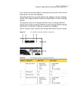
Page 17: ...k spins up Commands are processed Not lit Solid green Blinking green Blinking green occasionally Activity LED 2 See Appliance front panel LEDs on page 17 Appliance front panel LEDs Figure 2 2 Front panel LEDs Table 2 2 LED functions and indicators Description Number System ID button with integrated LED 1 Hard drive activity LED 2 ID button with integrated LED 3 17 LED status indicators Appliance f...

Page 18: ...D 9 Appliance status LED 10 See Appliance Ethernet port LEDs on page 18 Appliance Ethernet port LEDs Each Ethernet port on the rear panel of the appliance has two LEDs These LEDs indicate the status and the transmission rate of the network connection The following image shows the 1Gb Ethernet port LEDs Figure 2 3 1 Gb port LEDs The following table lists the 1 Gb Ethernet port LED indications 18 LE...

Page 19: ... to a tape library for offline storage Each port contains a Receive RX LED 1 and a Transmit TX LED 2 These LEDs show the type of input or output through each port Figure 2 4 8Gb FC HBA ports Each port on the 8Gb FC HBA card has three data transfer rate LEDs The LEDs are labeled 8 4 and 2 to correspond to the rate of data transfer 8Gbit s 4Gbit s or 2Gbit s Table 2 4 8Gb FC HBA data transfer rate L...

Page 20: ...E network ports for backup Figure 2 5 10GE ports Table 2 5 10GE LED indicators Description Status Color Type The link is normal and data transfers Flashes Green ACT LINK The link is normal On Green No link Off n a No link Off n a GRN 10G Data transfers at a rate of 10 Gbit s On Green Data transfers at a rate of 1 Gbit s On Yellow See Symantec Storage Shelf disk drive module and system LEDs on page...

Page 21: ...een Amber Red Global Enclosure Status 2 N A N A Reserved 3 Disk drive operation normal Disk drive fault Solid green Amber or red Disk status 4 Disk drive operation normal after appliance is turned on Disk activity is in progress Solid blue Flashing blue Disk Power activity 5 No activity Activity Not lit Flashes green I O module 1 activity 6 No activity Activity Not lit Flashes green I O module 2 a...

Page 22: ...bal Enclosure Status This LED is not in use at this time Off no light Reserved If one I O module in one storage shelf is properly connected to an external SAS port Flashes green once every 4 seconds Heartbeat If two I O modules in one storage shelf are properly connected to external SAS ports Flashes green once every 2 seconds Heartbeat See Symantec Storage Shelf disk drive module and system LEDs ...

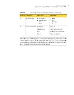
Page 23: ...age Shelf 4 Storage shelves 2 3 and 4 are not directly connected to the appliance One I O module is shown however each storage shelf includes two such modules Figure 2 7 I O module and power module components Table 2 8 I O module and power module descriptions Description LED states Component Number Link available Activity N A No link available Solid green Flashes green Red Not lit SAS_IN port LED ...

Page 24: ...wer not detected Solid green Flashes green Red Not lit Power module LED 6 Note When you start the Symantec Storage Shelf the primary I O module on the left side of the rear panel starts up first The LED turns green a few seconds after the main startup The LED of the secondary I O module on the right of the rear panel starts after the primary module is operational 24 LED status indicators Symantec ...

Page 25: ...harge Combustible gas Batteries Lasers Optical fibers Precautions when troubleshooting with the power turned on Lifting heavy objects Binding signal cables Overview Before you perform installation or maintenance operations learn the safety regulations of the site Read the safety precautions in this document for correct operating methods to ensure safety of persons and devices 3 Chapter ...
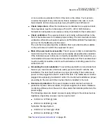
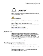
Page 26: ...learn the proper operating methods See Overview on page 25 Symbol conventions Warning symbols remind you of safety precautions to be followed during installation and maintenance operations Table 3 1 Warning symbols Description Symbol Indicates a hazard with a high level of risk that may result in death or serious injury Indicates a hazard with a medium or a low level of risk that can result in min...

Page 27: ...dia server before moving it Warning identifier against inserting and removing system disks You should not insert or remove system disks without following proper procedures Power warning identifier You must shut off all power sources when turning off a media server Identifier for reading the manual You must read the manual before operating the media server Drive identifier Indicates the ID number o...

Page 28: ...he socket outlet that the device plugs into should be installed near the equipment and should be easily accessible See Checking the resistance and voltage on page 51 High voltage precautions A high voltage power supply provides power for the device Direct or indirect contact through damp objects with a high voltage power supply including the main power in a building can result in fatal danger When...

Page 29: ...d make sure that the cord and label conform to the requirements for the installation Do not perform operations on high voltage power supplies and connections or other conductive materials during the storms which may produce lightening Be sure that all devices are properly grounded to prevent damage or injury during storms See ESD Electrostatic Discharge on page 29 ESD Electrostatic Discharge The s...

Page 30: ...ou can avoid short circuits of the devices that are caused by metallic tools See Combustible gas on page 30 Combustible gas Never place or operate a device in an environment with combustible or explosive gases or smoke Operations to any electronic devices in the presence of combustible gases cause an extreme danger See Batteries on page 30 Batteries Follow the safety precautions for operating lith...

Page 31: ...or protects the optical transceiver from the received optical power Disconnect the optical tail fibre between the peer device and the local device when you use the Optical Time Domain Effect Reflectometer OTDR Disconnecting the fibre protects the optical transceiver from the optical power source Do not remove or insert the optical transceiver that connects to the optical fibre without proper safet...

Page 32: ...Do not touch the connectors of power cords PDU cords or communication cables Otherwise you might receive an electrical shock Do not touch the device with bare hands in an electrostatic sensitive area To avoid personnel injuries or damage to the devices take ESD preventive measures If you touch power or PDU cords to perform operations when the power is on you must remove the ESD preventive wrist st...

Page 33: ...mly fixed on a wall or fixtures with enough load bearing capacity If a rope is used ensure that the angle between two sides of the rope is no larger than 90 Use simple and clear commands while speaking to personnel This approach helps to avoid any confusion that can cause accidents and damage to personnel or materials Binding signal cables Signal cables must be separately bundled from the strong c...

Page 34: ...shelf include the following Stay aware of general equipment status and current network activity Increase technical expertise with equipment and software to better address the issues that may arise or prevent possible issues Quickly and accurately identify and resolve alarms and problems See Maintenance requirements and timeframes on page 36 General rack installation guidelines Make sure that you g...

Page 35: ...ible for disconnection you must install an AC power disconnect for the entire rack unit This main disconnect must be readily accessible and it must be labeled as controlling power to the entire rack unit Grounding the rack installation To avoid the potential for an electrical shock hazard you must include a third wire safety ground conductor with the rack installation The rack itself must have a p...

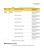
Page 36: ...ite Owner Daily Check equipment room and device surroundings Device site Maintenance engineers Monthly Check rack cabinet Daily for the first week of operation Then you can check weekly Check all indicator LEDs on the front panel of the device Daily for the first week of operation Then you can check weekly Check all indicator LEDs on the rear panel of the device 36 Maintenance guidelines Maintenan...

Page 37: ...s Daily for the first week of operation Then you can check weekly Check the fan status Daily for the first week of operation Then you can check weekly Check the power supply status Daily for the first week of operation Then you can check weekly Check the FC HBA status Daily for the first week of operation Then you can check weekly Check the 10GE NIC status Daily for the first week of operation The...

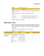
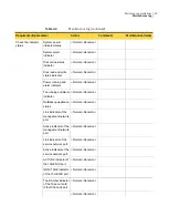
Page 38: ...eep a log of maintenance activities Consistent log keeping may help you identify trends or patterns to better maintain your equipment Electronic copies are recommended You can create a sortable spreadsheet to track issues See Maintenance requirements and timeframes on page 36 Table 4 3 Maintenance log MaintenanceOwner Comments Status Requirement parameter Normal Abnormal Operating temperature Chec...

Page 39: ...parameter Normal Abnormal Power system Check the environment inside the cabinet Normal Abnormal Cable system Normal Abnormal Grounding system Normal Abnormal Protective system Normal Abnormal Dust proof system Normal Abnormal Cable labeling 39 Maintenance guidelines Maintenance log ...

Page 40: ... Fan running and alarm indicator Normal Abnormal NetBackup appliance status Normal Abnormal Link indicator of the management network port Normal Abnormal Active indicator of the management network port Normal Abnormal Link indicator of the service network port Normal Abnormal Active indicator of the service network port Normal Abnormal ACT LNK indicator of the 10GE NIC port Normal Abnormal GRN 10G...

Page 41: ...annel port Normal Abnormal CPU status Checking on the system monitor interface CLI Normal Abnormal Disk status Normal Abnormal RAID status Normal Abnormal Fan status Normal Abnormal Power Supply status Normal Abnormal Temperature Normal Abnormal FC HBA status Problems and troubleshooting Remaining problems Verification Date See Maintenance requirements and timeframes on page 36 41 Maintenance guid...

Page 42: ...NetBackup Appliance Safety warnings and cautions Applications About equipment maintenance Equipment handling practices Rack mount guidelines Power and electrical warnings Power safety Power cord usage Power cord criteria AC power connections Checking the resistance and voltage Electrostatic discharge ESD Appliance shutdown and hardware access warnings 5 Chapter ...

Page 43: ...tions and approvals Use only the described regulated components that are specified in this guide Use of other products or components Voids the UL Listing Voids the regulatory approvals May result in noncompliance with product regulations in the region s where the product is sold or used May void the product warranty See Safety warnings and cautions on page 44 NetBackup appliance and Symantec Stora...

Page 44: ...commended that you install the devices from the bottom of the rack first Then install subsequent devices towards the top Locate the three screws projecting from the left and the right sides of the NetBackup appliance These three screws fit into the three slots in the rail extenders One fully loaded device weighs up to 33 kg 73 lbs More than two persons are required to move and install the device W...

Page 45: ...puter rooms and similar commercial type locations The suitability of this product for other product categories and environments other than an ITE application may require further evaluation Other product categories and environments include medical industrial residential alarm systems and test equipment See Product safety information on page 43 About equipment maintenance Environmental conditions su...

Page 46: ...ble components Do not touch fan blades to prevent injury Unplug all AC power cord s to disconnect AC power Please recycle all batteries See Power and electrical warnings on page 47 Rack mount guidelines The following are rack mount guidelines The equipment rack must be anchored to an unmovable support to prevent it from tipping when equipment is extended from it You must consider the weight of any...

Page 47: ... hazards The power button DOES NOT completely turn off the AC power A 5V standby power is active whenever the appliance is plugged in To remove power from the appliance you must completely unplug all the AC power cords from the wall outlets The appliance uses two AC power cords Make sure all AC power cords are unplugged Make sure the AC power cords are unplugged before you open the chassis or add ...

Page 48: ...quipment and should be easily accessible Power cord usage If an AC power cord was not provided with the product purchase two that are approved for use in your country To avoid electrical shock or fire check the power cords to be used with the product and read the following information Never attempt to modify or use the AC power cord s if they are not the exact type that is required for your locati...

Page 49: ...ctor appliance end The connectors that plug into the AC receptacle on the appliance must be an approved IEC International Electrotechnical Commission 320 sheet C13 type female connector Cord length and flexibility Cords must be less than 4 5 meters 14 76 feet long See Appliance shutdown and hardware access warnings on page 53 AC power connections NetBackup appliances and storage shelves currently ...

Page 50: ...U Figure 5 2 C14 plug to the PDU Table 5 2 C14 plug details Component color Number Green and yellow 1 Brown 2 Blue 3 Figure 5 3 Appliance AC power connections rear panel Note The highlighted area indicates the sockets to connect the PDU cords Verify that all power cords are connected properly 50 Detailed safety and maintenance information AC power connections ...

Page 51: ...ing of each rack cabinet component optional To check the resistance using the multimeter 1 Set the multimeter to the resistance position 2 Connect one lead to a fixed place in the equipment room You may need to extend the lead cable Use the other lead to measure each grounding point inside the cabinet 3 Given the measuring accuracy the measured resistance of each grounding point should be approxim...

Page 52: ...out equipment maintenance on page 45 Electrostatic discharge ESD ESD can damage disk drives boards and other parts We recommend that you perform all procedures at an ESD workstation If an ESD workstation is not available provide some ESD protection by wearing an antistatic wrist wrap The wrist wrap must be attached to chassis ground any unpainted metal surface on the appliance Always handle boards...

Page 53: ...de of the power supply there are no serviceable parts in the power supply When replacing a hot swappable power supply unplug the power cord to the power supply being replaced before removing the power supply from the appliance To avoid the possibility of coming into contact with hot component s during a hot swappable installation be careful when removing or installing the component s Contact Syman...

Page 54: ...connections on page 49 Bezel Check the bezel that is attached to the front panel The black molded plastic bezel protects the front panel from damage or accidental contact Proper air flow through the chassis may be impeded if there are problems with the bezel Verify that the bezel is Securely attached to the front panel Not damaged Not obstructed or blocked See Front and rear panels on page 53 Batt...

Page 55: ...g and airflow Carefully route cables as directed to minimize airflow blockage and cooling problems For proper cooling and airflow operate the appliance only with the chassis cover installed Operating the appliance without the chassis cover in place leads to a component damage caused due to unacceptable heat build up To install the cover Verify that you have not left tools or loose parts inside the...

Page 56: ...ersonal injury Do not open the enclosure of any laser peripheral or device Laser peripherals or devices are not user serviceable Return to manufacturer for servicing See Product safety information on page 43 56 Detailed safety and maintenance information Laser peripherals or devices ...

Page 57: ...Administrator Guide See Appliance induced shut down on page 57 Appliance induced shut down The terms protection or protected refer to a power supply that has shut down or locked up The appliance may turn off to protect itself and other components that are connected to the appliance A short circuit voltage overload or power surge can cause self protection If both power supplies are faulty do not at...

Page 58: ...nd back of the NetBackup Appliance are clear of any obstructions Air must flow easily and continually from the front of the appliance to the back of the appliance When the system alarm and location indicator on the appliance control panel is red the alarm information is displayed in the NetBackup Appliance Web Console The following types of information are shown Table 6 1 Temperature alarm informa...

Page 59: ...rces Shut down and disconnect any peripherals such as laptops storage devices or other servers See Temperature issues on page 58 Power supply module issues The two power supply modules are hot swappable However there must be one functioning power supply in the appliance at all times If a power supply is faulty order a new power supply quickly If there is only one functioning power supply the appli...

Page 60: ...x rated input AC current Max input AC current Power off VAC Startup VAC Max Rated Min Parameter 11 0 Arms 12 Arms 75 VAC 5VAC 85 VAC 5 VAC 140 Vrms 100 127 Vrms 90 Vrms Voltage 110 5 5 Arms 6 0 Arms 264 Vrms 200 240 Vrms 180 Vrms Voltage 220 63 Hz 50 60 Hz 47 Hz Frequency Important information about input current Maximum input AC current at low input voltage range is measured at 90 VAC at maximum ...

Page 61: ...non condensing at 28 C Non operating Humidity 2 0 g peak 11 msec half sine Non palletized free fall in height 24 40 lbs to 80 lbs Operational after an 18 free fall Trapezoidal 25 g velocity change 136 inches per sec Operating Packaged Unpackaged Shock 5 Hz to 500 Hz 2 20 g RMS random Unpackaged Vibration Sound Power 7 0 DBA in an idle state at typical office ambient temperature 23 2 C Acoustic noi...

Page 62: ... EMC Compliance Class A Compliance Product ecology compliance Certifications Registrations Declarations Electromagnetic compatibility notices FCC Verification Statement USA ICES 003 Canada CE Declaration of Conformity Europe VCCI Japan BSMI Taiwan Overview The following sections give information about the product regulations and compliance B Appendix ...

Page 63: ...require additional EMC compliance testing This product is an FCC Class A device Integration of it into a Class B system does not result in a Class B device See Product regulatory compliance on page 63 Product regulatory compliance The NetBackup appliance when correctly integrated per this guide complies with the following safety and electromagnetic compatibility EMC regulations Intended Applicatio...

Page 64: ... of EMC compliance norms for different countries FCC ICES 003 Emissions USA Canada Verification CISPR 22 Emissions International EN55022 Emissions Europe EN55024 Immunity Europe EN61000 3 2 Harmonics Europe EN61000 3 3 Voltage Flicker Europe CE EMC Directive 89 336 EEC Europe VCCI Emissions Japan AS NZS 3548 Emissions Australia New Zealand BSMI CNS13438 Emissions Taiwan GOST R 29216 91 Emissions R...

Page 65: ...tices for Perchlorate Materials China Restriction of Hazardous Substances China RoHS WEEE Directive Europe Packaging Directive Europe See Certifications Registrations Declarations on page 65 Certifications Registrations Declarations The following is a list of the required certifications registrations and declarations NRTL Certification US Canada CE Declaration of Conformity CENELEC Europe FCC ICES...

Page 66: ...ommunications However there is no guarantee that interference will not occur in a particular installation If this equipment does cause harmful interference to a radio or a television reception can be determined by turning the equipment off and on the user is encouraged to try to correct the interference by one or more of the following measures Reorient or relocate the receiving antenna Increase th...

Page 67: ...unications See CE Declaration of Conformity Europe on page 67 CE Declaration of Conformity Europe This product has been tested in accordance to and complies with the Low Voltage Directive 73 23 EEC and EMC Directive 89 336 EEC The product has been marked with the CE Mark to illustrate its compliance See VCCI Japan on page 67 VCCI Japan This is a Class A product based on the standard of the Volunta...

Page 68: ...ance 13 storage shelf 15 documentation 15 E electromagnetic compatibility BSMI Taiwan 67 CE declaration of conformity Europe 67 FCC USA 66 ICES 003 Canada 67 electromagnetic compatibility continued VCCI Japan 67 environmental specifications 61 F FTMS 11 L LEDs appliance 10GE card 20 8Gb FC HBA card 19 disk drives 16 Ethernet ports 18 system 17 storage shelf disk drive 20 I O modules 22 power modul...

Page 69: ...bustible gas 30 electrostatic discharge ESD 29 heavy objects 33 high voltage 28 identifier conventions 26 lasers 31 optical fibers 31 power on work 32 signal cables 33 symbol conventions 26 storage shelf dimensions 15 disk drive LEDs 20 fans 14 front panel 13 I O module 14 I O module LEDs 22 power module LED 22 power supplies 14 rear panel 13 system LEDs 20 weight 15 T temperature issues 58 W weig...

Reviews: