background image

AP-51xx Access Point Product Reference Guide

4-10

2.

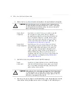
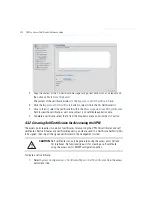
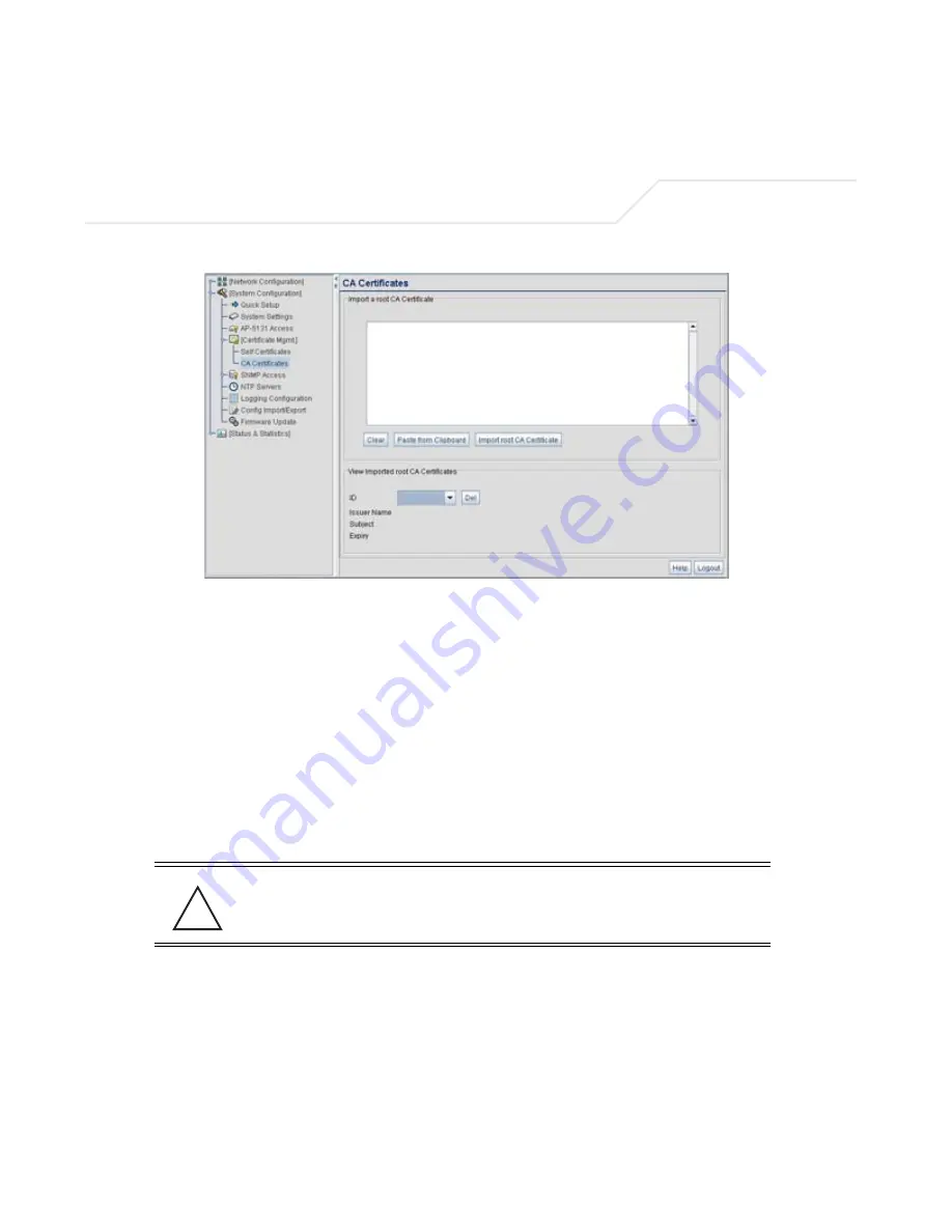
Copy the content of the CA Certificate message (using a text editor such as notepad) and 
then click on

 Paste from Clipboard

The content of the certificate displays in the 

Import a root CA Certificate

 field.

3.

Click the 

Import root CA Certificate

 button to import it into the CA Certificate list.

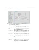
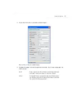
4.

Once in the list, select the certificate ID within the 

View Imported root CA Certificates


field to view the certificate issuer name, subject, and certificate expiration data.

5.

To delete a certificate, select the Id from the drop-down menu and click the 

Del

 button.

4.3.2 Creating Self Certificates for Accessing the VPN

The access point requires two kinds of certificates for accessing the VPN, CA certificates and self 
certificates. Self certificates are certificate requests you create, send to a Certificate Authority (CA) 
to be signed, then import the signed certificate into the management system. 

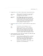
To create a self certificate:

1.

Select 

System Configuration 

-> 

Certificate Mgmt 

-> 

Self Certificates 

from the access 

point menu tree.

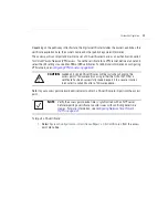
CAUTION

Self certificates can only be generated using the access point GUI and 
CLI interfaces. No functionality exists for creating a self-certificate 
using the access point’s SNMP configuration option.

!

Summary of Contents for AP-51 Series

Page 1: ...AP 51xx Access Point Product Reference Guide ...

Page 2: ......

Page 3: ...AP 51xx Access Point Product Reference Guide 72E XXXXX 01 Revision X Juanuary 2007 Pre Release ...

Page 4: ......

Page 5: ...rk from a licensed program or use a licensed program in a network without written permission from Symbol The user agrees to maintain Symbol s copyright notice on the licensed programs delivered hereunder and to include the same on any authorized copies it makes in whole or in part The user agrees not to decompile disassemble decode or reverse engineer any licensed program delivered to the user or ...

Page 6: ......

Page 7: ...Conventions viii Service Information viii Chapter 1 Introduction New Features 1 2 Mesh Networking 1 2 Additional LAN Subnet 1 3 On board Radius Server Authentication 1 4 Hotspot Support 1 4 Routing Information Protocol RIP 1 5 Manual Date and Time Settings 1 5 Feature Overview 1 6 ...

Page 8: ...802 11i Encryption 1 13 Firewall Security 1 14 VPN Tunnels 1 14 Content Filtering 1 14 VLAN Support 1 14 Multiple Management Accessibility Options 1 15 Updatable Firmware 1 15 Programmable SNMP v1 v2 v3 Trap Support 1 15 Power over Ethernet Support 1 16 MU MU Transmission Disallow 1 16 Voice Prioritization 1 17 Support for CAM and PSP MUs 1 17 Statistical Displays 1 17 Transmit Power Control 1 18 ...

Page 9: ...AP 5131 Power Options 2 8 AP 5181 Power Options 2 8 Symbol Power Injector System 2 9 Installing the Power Injector 2 9 Preparing for Site Installation 2 10 Cabling the Power Injector 2 10 Power Injector LED Indicators 2 11 Mounting the AP 5131 2 12 Desk Mounted Installations 2 12 Wall Mounted Installations 2 14 Suspended Ceiling T Bar Installations 2 16 Above the Ceiling Plenum Installations 2 18 ...

Page 10: ...cate for Onboard Radius Authentication 4 13 Configuring SNMP Settings 4 17 Configuring SNMP Access Control 4 22 Enabling SNMP Traps 4 24 Configuring Specific SNMP Traps 4 27 Configuring SNMP RF Trap Thresholds 4 29 Configuring Network Time Protocol NTP 4 31 Logging Configuration 4 34 Importing Exporting Configurations 4 36 Updating Device Firmware 4 40 Upgrade Downgrade Considerations 4 45 Chapter...

Page 11: ... Resetting the Access Point Password 6 4 Enabling Authentication and Encryption Schemes 6 5 Configuring Kerberos Authentication 6 9 Configuring 802 1x EAP Authentication 6 11 Configuring WEP Encryption 6 16 Configuring KeyGuard Encryption 6 18 Configuring WPA Using TKIP 6 20 Configuring WPA2 CCMP 802 11i 6 22 Configuring Firewall Settings 6 25 Configuring LAN to WAN Access 6 27 Available Protocols...

Page 12: ... 7 11 Viewing WLAN Statistics 7 13 Viewing Radio Statistics Summary 7 17 Viewing Radio Statistics 7 18 Retry Histogram 7 21 Viewing MU Statistics Summary 7 23 Viewing MU Details 7 24 Pinging Individual MUs 7 27 MU Authentication Statistics 7 28 Viewing the Mesh Statistics Summary 7 29 Viewing Known Access Point Statistics 7 30 Chapter 8 Command Line Interface Reference Connecting to the CLI 8 1 Ac...

Page 13: ...stem Certificate Management Commands 8 139 System SNMP Commands 8 152 System SNMP Access Commands 8 153 System SNMP Traps Commands 8 158 System Network Time Protocol NTP Commands 8 164 System Log Commands 8 169 System Configuration Update Commands 8 175 Firmware Update Commands 8 182 Statistics Commands 8 186 Chapter 9 Configuring Mesh Networking Mesh Networking Overview 9 1 The AP 51xx Client Bri...

Page 14: ...enna Specifications A 5 AP 5131 Antenna Specifications A 5 2 4 GHz Antenna Matrix A 5 5 2 GHz Antenna Matrix A 5 AP 5131 Additional Antenna Components A 6 AP 5131 Antenna Accessory Connectors Cable Type and Length A 6 AP 5181 Antenna Specifications A 7 Country Codes A 7 Appendix B Usage Scenarios Configuring Automatic Updates using a DHCP or Linux BootP Server ConfigurationB 1 Windows DHCP Server ...

Page 15: ...xi Frequently Asked VPN Questions B 13 Replacing an AP 4131 with an AP 5131 or AP 5181 B 18 Appendix C Customer Support Index ...

Page 16: ...AP 51xx Access Point Product Reference Guide xii ...

Page 17: ...81 model access points For the purposes of this guide the devices will be called AP 51xx or the generic term access point when an identical conifiguration activities applied to both models Document Conventions The following document conventions are used in this document NOTE Indicate tips or special requirements ...

Page 18: ...e Symbol Customer Support Refer to Appendix C for contact information Before calling have the model number and serial number at hand If the problem cannot be solved over the phone you may need to return your equipment for servicing If that is necessary you will be given specific instructions Symbol Technologies is not responsible for any damages incurred during shipment if the approved shipping co...

Page 19: ...or deployments The access point AP provides a bridge between Ethernet wired LANs or WANs and wireless networks It provides connectivity between Ethernet wired networks and radio equipped mobile units MUs MUs include the full line of Symbol terminals bar code scanners adapters PC cards Compact Flash cards and PCI adapters and other devices The access point provides a maximum 54Mbps data transfer ra...

Page 20: ...wireless connection The mesh networking association process is identical to the access point s MU association process Once the association authentication process is complete the wireless client adds the connection as a port on its bridge module This causes the access point in client bridge mode to begin forwarding configuration packets to the base bridge An access point in base bridge mode allows ...

Page 21: ...etworking on page 9 1 1 1 2 Additional LAN Subnet In a typical retail or small office environment wherein a wireless network is available along with a production WLAN it is frequently necessary to segment a LAN into two subnets Consequently a second LAN is necessary to segregate wireless traffic The access point now has a second LAN subnet enabling administrators to segment the access point s LAN ...

Page 22: ...t The access point now allows hotspot operators to provide user authentication and accounting without a special client application The access point uses a traditional Internet browser as a secure authentication device Rather than rely on built in 802 11security features to control access point association privileges you can configure a WLAN with no WEP an open network The access point issues an IP...

Page 23: ...uthentication used For detailed information on configuring RIP functionality as part of the access point s Router functionality see Setting the RIP Configuration on page 5 58 1 1 6 Manual Date and Time Settings As an alternative to defining a NTP server to provide access point system time the access point can now have its date and time set manually A new Manual Date Time Setting screen can be used...

Page 24: ...nfigurable WLANs Support for 4 BSSIDs per Radio Quality of Service QoS Support Industry Leading Data Security VLAN Support Multiple Management Accessibility Options Updatable Firmware Programmable SNMP v1 v2 v3 Trap Support Power over Ethernet Support MU MU Transmission Disallow Voice Prioritization Support for CAM and PSP MUs Statistical Displays Transmit Power Control Advanced Event Logging Capa...

Page 25: ...t For detailed information on configuring the access point LAN port see Configuring the LAN Interface on page 5 1 A Wide Area Network WAN is a widely dispersed telecommunications network In a corporate environment the WAN port might connect to a larger corporate network For a small business the WAN port might connect to a DSL or cable modem to access the Internet Regardless network address informa...

Page 26: ...rs can be handed off from one access point to another like a cellular phone system WLANs can therefore be configured around the needs of specific groups of users even when they are not in physical proximity Sixteen WLANs are configurable on each access point To enable and configure WLANs on an access point radio see Enabling Wireless LANs WLANs on page 5 22 1 2 6 Support for 4 BSSIDs per Radio The...

Page 27: ...Introduction 1 9 For detailed information on strategically mapping BSSIDs to WLANs see Configuring the 802 11a or 802 11b g Radio on page 5 47 ...

Page 28: ...ansmitting higher priority data traffic and is thus desirable for multimedia applications In addition U APSD WMM Power Save is also supported WMM defines four access categories voice video best effort and background to prioritize traffic for providing enhanced multimedia support For detailed information on configuring QoS support for the access point see Setting the WLAN Quality of Service QoS Pol...

Page 29: ...ng of RFC 1510 Kerberos Network Authentication Service V5 is helpful in understanding how Kerberos functions By default WLAN devices operate in an open system network where any wireless device can associate with an AP without authorization Kerberos requires device authentication before access to the wired network is permitted For detailed information on Kerbeors configurations see Configuring Kerb...

Page 30: ...r or front end processor usually performs both encryption and decryption The data transmit or receive direction determines whether the encryption or decryption function is performed The device takes plain text encrypts or scrambles the text typically by mathematically combining the key with the plain text as instructed by the algorithm then transmits the data over the network At the receiving end ...

Page 31: ...eying mechanism WPA uses an encryption method called Temporal Key Integrity Protocol TKIP WPA employs 802 1X and Extensible Authentication Protocol EAP For detailed information on WPA using TKIP configurations see Configuring WPA Using TKIP on page 6 20 1 2 8 6 WPA2 CCMP 802 11i Encryption WPA2 is a newer 802 11i standard that provides even stronger wireless security than Wi Fi Protected Access WP...

Page 32: ...rough the public network it needs several layers of security The access point can function as a robust VPN gateway For detailed information on configuring VPN security support see Configuring VPN Tunnels on page 6 33 1 2 8 9 Content Filtering Content filtering allows system administrators to block specific commands and URL extensions from going out through the access point WAN port only Therefore ...

Page 33: ... port for direct access to the command line interface from a PC Use Symbol s Null Modem cable Part No 25 632878 0 for the best fitting connection 1 2 11 Updatable Firmware Symbol periodically releases updated versions of the access point device firmware to the Symbol Web site If the access point firmware version displayed on the System Settings page see Configuring System Settings on page 4 2 is o...

Page 34: ...d power source was required for each access point in addition to the Ethernet infrastructure This often required an electrical contractor to install power drops at each access point location An approved power injector solution merges power and Ethernet into one cable reducing the burden of installation and allows optimal access point placement in respect to the intended radio coverage area An AP 5...

Page 35: ... 5 33 1 2 16 Support for CAM and PSP MUs The access point supports both CAM and PSP powered MUs CAM Continuously Aware Mode MUs leave their radios on continuously to hear every beacon and message transmitted These systems operate without any adjustments by the access point A beacon is a uniframe system packet broadcast by the AP to keep the network synchronized A beacon includes the ESSID access p...

Page 36: ...page 5 47 1 2 19 Advanced Event Logging Capability The access point provides the capability for periodically logging system events Logging events is useful in assessing the throughput and performance of the access point or troubleshooting problems on the access point managed Local Area Network LAN For detailed information on access point events see Logging Configuration on page 4 34 1 2 20 Configu...

Page 37: ...e server is running BOOTP exclusively The DHCP client automatically sends a DHCP request at an interval specified by the DHCP server to renew the IP address lease as long as the access point is running this parameter is programmed at the DHCP server For example Windows 2000 servers typically are set for 3 days 1 2 23 Multi Function LEDs The access point houses seven LED indicators Four LEDs exist ...

Page 38: ...ium The access point can either transmit in the 2 4 to 2 5 GHz frequency range 802 11b g radio or the 5 2 GHz frequency range 802 11a radio the actual range is country dependent Symbol devices like other Ethernet devices have unique hardware encoded Media Access Control MAC or IEEE addresses MAC addresses determine the device sending or receiving data A MAC address is a 48 bit number written as si...

Page 39: ...even when they are not in physical proximity 1 3 2 MAC Layer Bridging The access point provides MAC layer bridging between its interfaces The access point monitors traffic from its interfaces and based on frame address forwards the frames to the proper destination The access point tracks source and destination addresses to provide intelligent bridging as MUs roam or network topologies change The a...

Page 40: ...ectrum Spread spectrum broadband uses a narrowband signal to spread the transmission over a segment of the radio frequency band or spectrum Direct sequence is a spread spectrum technique where the transmitted signal is spread over a particular frequency range The Symbol access point uses Direct Sequence Spread Spectrum DSSS for radio communication Direct sequence systems communicate by continuousl...

Page 41: ...full or partial scans to collect access point statistics and determine the direct sequence channel used by the access point Scanning is a periodic process where the MU sends out probe messages on all channels defined by the country code The statistics enable an MU to reassociate by synchronizing its channel to the access point The MU continues communicating with that access point until it needs to...

Page 42: ...WLANs Each WLAN can be configured to be broadcast by one or both access point radios unlike the AP 4131 model access point An AP 5131 or AP 5181 can operate in both an Access Point mode and Wireless Gateway Router mode simultaneously The network architecture and access point configuration define how the Access Point and Wireless Gateway Router mode are negotiated Wireless Gateway Router If operati...

Page 43: ... s Java Virtual Machine if installed Command Line Interface CLI via Serial Telnet and SSH Config file Human readable Importable Exportable via FTP and TFTP MIB Management Information Base accessing the access point SNMP function using a MIB Browser The AP 5131 or AP 5181 downloads site contains the following 2 MIB files Symbol CC WS2000 MIB 2 0 standard Symbol MIB file Symbol AP 5131 MIB AP 5131 a...

Page 44: ...AP 51xx Access Point Product Reference Guide 1 26 ...

Page 45: ...onnection connecting antennae and applying power Installation procedures vary for different environments See the following sections for more details Precautions Requirements Access Point Placement Power Options Symbol Power Injector System Mounting the AP 5131 AP 5131 LED Indicators Mounting the AP 5181 AP 5181 LED Indicators Mounting the AP 5181 ...

Page 46: ...ol recommends conducting a radio site survey prior to installing the access point A site survey is an excellent method of documenting areas of radio interference and providing a tool for device placement Symbol Part Description AP 5131 13040 WW AP 5131 802 11a g Dual Radio Access Point AP 5131 Install Guide Software and Documentation CD ROM Accessories Bag AP 5131 13041 WWR AP 5131 802 11a g Dual ...

Page 47: ...02 11a g Single Radio Access Point AP 5131 Install Guide Software and Documentation CD ROM Accessories Bag AP 5131 40021 WWR AP 5131 802 11a g Single Radio Access Point AP 5131 Install Guide Software and Documentation CD ROM Power Injector Part No AP PSBIAS 1P2 AFR Accessories Bag AP 5131 40022 WW AP 5131 802 11a g Single Radio Access Point AP 5131 Install Guide Software and Documentation CD ROM 2...

Page 48: ...ations on the 2 4 GHz and 5 2 GHz antenna suite see 2 4 GHz Antenna Matrix on page A 5 and 5 2 GHz Antenna Matrix on page A 5 2 2 2 AP 5181 Configurations TBD CAUTION Using an antenna other than the Dual Band Antenna Part No ML 2452 APA2 01 could render the AP 5131 s Rogue AP Detector Mode feature inoperable Contact your Symbol sales associate for specific information ...

Page 49: ... add access points as needed to improve coverage Antenna coverage is analogous to lighting Users might find an area lit from far away to be not bright enough An area lit sharply might minimize coverage and create dark areas Uniform antenna placement in an area like even placement of a light bulb provides even efficient coverage Place the access point using the following guidelines Install the acce...

Page 50: ...formance and signal reception Symbol supports two antenna suites for the AP 5131 One antenna suite supporting the 2 4 GHz band and another antenna suite supporting the 5 2 GHz band Select an antenna model best suited to the intended operational environment of your AP 5131 Antenna connectors for Radio 1 are located in a different location from the Radio 2 antenna connectors On single radio versions...

Page 51: ...ectional 8 5 ML 2499 HPA3 01R Omni Directional Antenna 3 3 ML 2499 BYGA2 01R Yagi Antenna 13 9 ML 2452 APA2 01 Dual Band 3 0 NOTE An additional adapter is required to use ML 2499 11PNA2 01 and ML 2499 BYGA2 01 model antennae Please contact Symbol for more information Symbol Part Number Antenna Type Nominal Net Gain dBi ML 5299 WPNA1 01R Panel Antenna 13 0 ML 5299 HPA1 01R Wide Band Omni Directiona...

Page 52: ...wer Injector Part No AP PSBIAS 1P2 AFR Symbol 48 Volt Power Supply Part No 50 24000 050 Any standard 802 3af compliant device 2 5 2 AP 5181 Power Options The power options for the AP 5181 include Symbol Power Injector Part No AP PSBIAS 1P2 AFR Symbol AP 5181 specific 48 Volt Power Supply Part No AP PSBIAS 5181 01R Any standard 802 3af compliant device CAUTION An AP 5181 model access point cannot u...

Page 53: ...1P2 AFR is an integrated AC DC converter and 802 3af power injector which requires 110 220V AC power to combine low voltage DC with Ethernet data in a single cable connecting to the access point The access point can only use a Power Injector when connected to the LAN port The Symbol AP 5131 and AP 5181 Power Supply Part Numbers 50 24000 050 and AP PSBIAS 5181 01R respectively are not included in t...

Page 54: ...port 2 6 1 2 Cabling the Power Injector To install the power injector to an Ethernet data source and access point 1 Connect the power injector to an AC outlet 110VAC to 220VAC 2 Connect an RJ 45 Ethernet cable between the network data supply host and the power injector Data In connector 3 Connect an RJ 45 Ethernet cable between the power injector Data Power Out connector and the Symbol access poin...

Page 55: ...der normal and or problematic operating conditions For more information and device specifications for the Symbol power injector refer to the Power Injector Quick Install Guide Part No 72 70762 01 available from the Symbol Web site LED AC Main Port Green Steady Power injector is receiving power from AC outlet Indicates a device is connected to the power injector s outgoing Data Power cable Green Bl...

Page 56: ...et can be found in the AP 5131 main box in a separate plastic bag To install the AP 5131 in a desk mount orientation 1 Turn the AP 5131 upside down 2 Attach the radio antennae to their correct connectors The antenna protection plate cannot be used in a desk mount configuration as the plate only allows antennas to be positioned in a downward orientation 3 Remove the backings from the four 4 rubber ...

Page 57: ...ft The power injector has no On Off power switch The power injector receives power as soon as AC power is applied For more information on using the power injector see Symbol Power Injector System on page 2 9 For standard Symbol 48 Volt power adapter Part No 50 24000 050 and line cord installations a Connect RJ 45 Ethernet cable between the network data supply host and the AP 5131 LAN port b Verify...

Page 58: ...a wall consists of Two Phillips pan head self tapping screws ANSI Standard 6 18 X 0 875in Type A or AB Self Tapping screw or ANSI Standard Metric M3 5 X 0 6 X 20mm Type D Self Tapping screw Two wall anchors Security cable optional To mount the AP 5131 on a wall 1 Orient the AP 5131 on the wall by its width or length 2 Using the arrows on one edge of the case as guides move the edge to the midline ...

Page 59: ...50 and line cord installations a Connect RJ 45 Ethernet cable between the network data supply host and the AP 5131 LAN port b Verify the power adapter is correctly rated according the country of operation c Connect the power supply line cord to the power adapter d Attach the power adapter cable into the power connector on the AP 5131 CAUTION Both the Dual and Single Radio model AP 5131s use RSMA t...

Page 60: ...AP 5131 on a ceiling T bar 1 If required loop a safety wire with a diameter of at least 1 01 mm 04 in but no more than 0 158 mm 0625 in through the tie post above the AP 5131 s console connector and secure the loop 2 If required install and attach a security cable to the AP 5131 lock port 3 Attach the radio antennae to their correct connectors NOTE If the AP 5131 is utilizing remote management ant...

Page 61: ...ations a Connect RJ 45 Ethernet cable between the network data supply host and the AP 5131 LAN port b Verify the power adapter is correctly rated according the country of operation c Connect the power supply line cord to the power adapter d Attach the power adapter cable into the power connector on the AP 5131 e Plug the power adapter into an outlet 5 Verify the behavior of the AP 5131 LEDs For mo...

Page 62: ...e ceiling installation requires placing the AP 5131 above a suspended ceiling and installing the provided light pipe under the ceiling tile for viewing the rear panel status LEDs of the unit An above the ceiling AP 5131 installation enables installations compliant with drop ceilings suspended ceilings and industry standard tiles from 625 to 75 inches thick NOTE If the AP 5131 is utilizing remote m...

Page 63: ... hole in the tile the approximate size of the AP 5131 LED light pipe 7 Remove the light pipe s rubber stopper before installing the light pipe 8 Connect the light pipe to the bottom of the AP 5131 Align the tabs and rotate approximately 90 degrees Do not over tighten CAUTION Symbol does not recommend mounting the AP 5131 directly to any suspended ceiling tile with a thickness less than 12 7mm 0 5i...

Page 64: ... its former ceiling space 15 Cable the AP 5131 using either the Symbol power injector solution or an approved line cord and power supply CAUTION Both the Dual and Single Radio model AP 5131s use RSMA type antenna connectors On the Dual Radio AP 5131 a single dot on the antenna connector indicates the primary antenna for both Radio 1 2 4 GHz and Radio 2 5 2 GHz Two dots designate the secondary ante...

Page 65: ... and the AP 5131 LAN port b Verify the power adapter is correctly rated according the country of operation c Connect the power supply line cord to the power adapter d Attach the power adapter cable into the power connector on the AP 5131 e Plug the power adapter into an outlet 16 Verify the behavior of the AP 5131 LED lightpipe For more information see AP 5131 LED Indicators on page 2 21 17 Place ...

Page 66: ...tpipe have the following color display and functionality Power Status Solid white indicates the AP 5131 is adequately powered Error Conditions Solid red indicates the AP 5131is experiencing a problem condition requiring immediate attention Ethernet Activity Flashing white indicates data transfers and Ethernet activity 802 11a Radio Activity Flickering amber indicates beacons and data transfers ove...

Page 67: ...flat side of the rectangular plate The inner slots are for the 1 5 inch diameter pole and the outer slots for a 2 inch diameter pole 2 Place the V shaped bracket clamp parts around the pole and tighten the nuts just enough to hold the bracket to the pole The bracket may need to be rotated around the pole during the antenna alignment process 3 Attach the square mounting plate to the bridge with the...

Page 68: ...s of the four mounting screw holes 2 Drill four holes in the wall that match the screws and wall plugs 3 Secure the bracket to the wall 4 Attach the square mounting plate to the bridge with the supplied screws Attach the bridge to the plate on the pole 5 Use the included nuts to tightly secure the wireless bridge to the bracket NOTE The AP 5181 tilt angle may need to be adjusted during the antenna...

Page 69: ...ghtpipe adjusted as required to suit above the ceiling installations Power Status Solid white indicates the AP 5131 is adequately powered Error Conditions Solid red indicates theAP 5131is experiencing a problem condition requiring immediate attention Ethernet Activity Flashing white indicates data transfers and Ethernet activity 802 11a Radio Activity Flickering amber indicates beacons and data tr...

Page 70: ...Card and PCI Adapter Users Guide available from the Symbol Web site for installing drivers and client software if operating in an 802 11a g network environment Refer to the Spectrum24 LA 4121 PC Card LA 4123 PCI Adapter LA 4137 Wireless Networker User Guide available from the Symbol Web site for installing drivers and client software if operating in an 802 11b network environment Use the default v...

Page 71: ...outlined in Appendix 2 Hardware Installation on page 2 1 See the following sections for more details Installing the Access Point Configuration Options Basic Device Configuration 3 1 Installing the Access Point Make the required cable and power connections before mounting the access point in its final operating position Test the access point with an associated MU before mounting and securing the ac...

Page 72: ...access point see Symbol Power Injector System on page 2 9 To verify AP 5131 LED behavior once installed see AP 5131 LED Indicators on page 2 21 To verify the behavior of the AP 5181 LEDs once installed see AP 5181 LED Indicators on page 2 25 3 2 Configuration Options Once installed and powered the access point can be configured using one of several connection techniques Managing the access point i...

Page 73: ...specific MIB file 3 3 Basic Device Configuration For the basic setup described in this section the Java based Web UI will be used to configure the access point Use the access point s LAN interface for establishing a link with the access point Configure the access point as a DHCP client For optimal screen resolution set your screen resolution to 1024 x 768 pixels or greater 1 Start Internet Explore...

Page 74: ... for an AP 5131 there is no difference for an AP 5181 3 If the default login is successful the Change Admin Password window displays Change the password Enter the current password and a new admin password in fields provided and click Apply Once the admin password has been updated a warning message displays stating the access point must be set to a country ...

Page 75: ...the access point s country of operation from the drop down menu The access point prompts the user for the correct country code on the first login A warning message also displays stating that an incorrect country settings may result in illegal radio operation Selecting the correct country is central to legally operating the access point Each country has its own regulatory restrictions concerning el...

Page 76: ...rger network or the Internet will be possible MUs cannot communicate beyond the configured subnets b Select the This Interface is a DHCP Client checkbox to enable DHCP for the access point WAN connection This is useful if the larger corporate network or Internet Service Provider ISP uses DHCP DHCP is a protocol that includes mechanisms for IP address allocation and delivery of host specific config...

Page 77: ...Specify a Username entered when connecting to the ISP When the Internet session begins the ISP authenticates the username c Specify a Password entered when connecting to the ISP When the Internet session starts the ISP authenticates the password For additional access point WAN port configuration options see Configuring WAN Settings on page 5 14 7 Click the LAN tab to set a minimum set of parameter...

Page 78: ...signed to another client To avoid this ensure all statically mapped IP addresses are outside of the IP address range assigned to the DHCP server For additional access point LAN port configuration options see Configuring the LAN Interface on page 5 1 8 Enable the radio s using the Enable checkbox es within the Radio Configuration field If using a single radio access point enable the radio then sele...

Page 79: ...es to the access point Quick Setup screen Navigating away from the screen without clicking Apply results in all changes to the screens being lost 11 Click Undo Changes if necessary to undo any changes made Undo Changes reverts the settings displayed on the access point Quick Setup screen to the last saved configuration 3 3 1 1 Configuring WLAN Security Settings To configure a basic security policy...

Page 80: ... WEP 128 Settings field displays within the New Security Policy screen 4 Configure the WEP 128 Settings field as required to define the Pass Key used to generate the WEP keys Pass Key Specify a 4 to 32 character pass key and click the Generate button The access point other proprietary routers and Symbol MUs use the same algorithm to convert an ASCII string to the same hexadecimal number Non Symbol...

Page 81: ...s to specify key numbers The key can be either a hexidecimal or ASCII depending on which option is selected from the drop down menu For WEP 64 40 bit key the keys are 10 hexadecimal characters in length or 5 ASCII characters For WEP 128 104 bit key the keys are 26 hexadecimal characters in length or 13 ASCII characters Select one of these keys for activation by clicking its radio button The access...

Page 82: ...f the network and the users it supports Refer to the following For detailed information on access point device access SNMP settings network time importing exporting device configurations and device firmware updates see Chapter 4 System Configuration on page 4 1 For detailed information on configuring access point LAN interface subnet and WAN interface see Chapter 5 Network Management on page 5 1 F...

Page 83: ... the access point requires either Microsoft Internet Explorer 5 0 or later or Netscape Navigator 6 0 or later To connect to the AP the access point IP is required Enter 192 168 0 1 for the default IP address The password is symbol NOTE For optimum compatibility use Sun Microsystems JRE 1 5 or higher available from Sun s Web site and be sure to disable Microsoft s Java Virtual Machine if installed ...

Page 84: ...ce Firmware 4 1 Configuring System Settings Use the System Settings screen to specify the name and location of the access point assign an email address for the network administrator restore the AP s default configuration or restart the AP To configure System Settings for the access point 1 Select System Configuration System Settings from the access point menu tree 2 Configure the access point Syst...

Page 85: ...trictions concerning electromagnetic emissions channel range and the maximum RF signal strength transmitted To ensure compliance with national and local laws be sure to set the Country field correctly If using the access pointconfiguration file CLI or MIB to configure the access point s country code see Country Codes on page A 7 access point Version The displayed number is the current version of t...

Page 86: ...rt screen to export the current configuration for safekeeping see Importing Exporting Configurations on page 4 36 Restore Partial Default Configuration Select the Restore Partial Default Configuration button to restore a default configuration with the exception of the current LAN WAN SNMP settings and IP address used to launch the browser If selected a message displays warning the user all current...

Page 87: ...passwords Use the access point Access screen checkboxes to enable or disable LAN1 LAN2 and or WAN access using the protocols and ports listed If access is disabled this effectively locks out the administrator from configuring the access point using that interface To avoid jeopardizing the network data managed by the access point Symbol recommends enabling only those interfaces used in the routine ...

Page 88: ...s point configuration applet using a Secure Sockets Layer SSL for encrypted HTTP sessions CLI TELNET port 23 Select the LAN1 LAN2 and or WAN checkboxes to enable access to the access point CLI via the TELNET terminal emulation TCP IP protocol CLI SSH port 22 Select the LAN1 LAN2 and or WAN checkboxes to enable access to the access point CLI using the SSH Secure Shell protocol SNMP port 161 Select ...

Page 89: ... Defining a Keepalive interval is important otherwise programs running on a server may never notice if the other end of a connection is rebooted Local The access point verifies the authentication connection Radius Designates that a Radius server is used in the authentication credential verification If using this option the connected PC is required to have its Radius credentials verified with an ex...

Page 90: ... CA is a network authority that issues and manages security credentials and public keys for message encryption The CA signs all digital certificates that it issues with its own private key The corresponding public key is contained within the certificate and is called a CA certificate A browser must contain this CA certificate in its Trusted Root Library so that it can trust certificates signed by ...

Page 91: ... Tunnels on page 6 33 Refer to your access point network administrator to obtain a CA certificate to import into the access point To import a CA certificate 1 Select System Configuration Certificate Mgmt CA Certificates from the access point menu tree CAUTION Loaded and signed CA certificates will be lost when changing the access point s firmware version using either the GUI or CLI After a certifi...

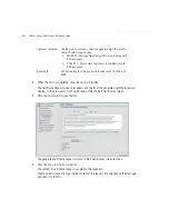
Page 92: ...certificate select the Id from the drop down menu and click the Del button 4 3 2 Creating Self Certificates for Accessing the VPN The access point requires two kinds of certificates for accessing the VPN CA certificates and self certificates Self certificates are certificate requests you create send to a Certificate Authority CA to be signed then import the signed certificate into the management s...

Page 93: ...nt information Only 4 values are required the others optional Key ID Enter a logical name for the certificate to help distinguish between certificates The name can be up to 7 characters in length Subject The required Subject value contains important information about the certificate Contact the CA signing the certificate to determine the content of the Subject parameter ...

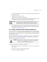
Page 94: ...tificates screen text box 6 Click the Copy to Clipboard button The content of certificate request is copied to the clipboard Create an email to your CA paste the content of the request into the body of the message and send it to the CA Signature Algorithm Use the drop down menu to select the signature algorithm used for the certificate Options include MD5 RSA Message Digest 5 algorithm in combinat...

Page 95: ...e certificate before downloading it back to the access point s on board Radius server and loading the certificate for use with the access point Both a CA and Self certificate are required for Onboard Radius Authentication For information on CA Certificates see Importing a CA Certificate on page 4 8 Ensure the certificate is in a Base 64 Encoded format or risk loading an invalid certificate To crea...

Page 96: ...ity where the access point using the certificate resides State Optionally enter the name of the State where the access point using the certificate resides Postal Code Optionally enter the name of the Postal Zip Code where the access point using the certificate resides Country Code Optionally enter the access point s Country Code Email Enter a organizational email address avoid using a personal add...

Page 97: ...screen The certificate content displays within the Self Certificate screen 7 Click the Copy to clipboard button Save the certificate content to a secure location 8 Connect to the Windows 2000 or 2003 server used to sign the certificate 9 Select the Request a certificate option Click Next to continue Key Length Defines the length of the key Possible values are 512 1024 and 2048 Symbol recommends se...

Page 98: ...ificate to a secure location 15 Load the certificates on the access point 16 Open the certificate file and copy its contents into the CA Certificates screen by clicking the Paste from Clipboard button The certificate is now ready to be loaded into the access point s flash memory 17 Click the Import root CA Certificate button from within the CA Certificates screen 18 Verify the contents of the cert...

Page 99: ... MIB contains the majority of the information contained within the Symbol CC WS2000 MIB 2 0 file This feature rich information has been validated with the Symbol WS2000 and proven reliable The remaining portion of the Symbol AP 5131 MIB contains supplemental information unique to the access point feature set Feature MIB Feature MIB LAN Configuration Symbol AP 5131 MIB Subnet Configuration Symbol C...

Page 100: ...esholds Symbol AP 5131 MIB LAN to WAN Access Symbol CC WS2000 MIB 2 0 Config Import Export Symbol AP 5131 MIB AdvancedLANAccess Symbol CC WS2000 MIB 2 0 MU Authentication Stats Symbol AP 5131 MIB Router Configuration Symbol CC WS2000 MIB 2 0 Feature MIB Feature MIB WNMP Ping Configuration Symbol AP 5131 MIB System Settings Symbol CC WS2000 MIB 2 0 Known AP Stats Symbol AP 5131 MIB AP 5131 Access S...

Reviews: