background image

M

D

M


3

0

0

0


S

e

r

i

e

s


M

o

d

e

m


M

o

d

u

l

e

Summary of Contents for MDM 3000 Series

Page 1: ...M D M 3 0 0 0 S e r i e s M o d e m M o d u l e ...

Page 2: ...247 162 5 250 791 5 250 792 5 260 553 5 262 627 5 262 628 5 266 787 5 278 398 5 280 162 5 280 163 5 280 164 5 280 498 5 304 786 5 304 788 5 306 900 5 321 246 5 324 924 5 337 361 5 367 151 5 373 148 5 378 882 5 396 053 5 396 055 5 399 846 5 408 081 5 410 139 5 410 140 5 412 198 5 418 812 5 420 411 5 436 440 5 444 231 5 449 891 5 449 893 5 468 949 5 471 042 5 478 998 5 479 000 5 479 002 5 479 441 5 ...

Page 3: ...ring removing and using the MDM 3000 MDM 3000 Ports Installing the MDM 3000 To install place the MDM 3000 on the bottom of the terminal as shown ensuring it snaps into place Removing the MDM 3000 To remove grasp the sides of the modem module and gently pull the modem off the terminal Charging the Terminal s Battery The terminal s battery can be charged while the MDM 3000 is in place on the bottom ...

Page 4: ... the MDM 3000 Connect an RJ11 cable 1 Insert the RJ11 connector on the cable into the modem port on the MDM 3000 2 Connect the other end to an analog telephone jack on the wall Note The middle two pins of the connector provide the signal to the MDM3000 Caution To reduce the risk of fire use only No 26 AWG or larger telecommunication line cord Using the Correct Telephone Line Type Use a standard an...

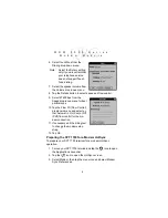
Page 5: ...on 3 5 use PowerDrv35 prc HotSync the driver to your SPT 1700 terminal and perform a soft reset To define modem connection settings 1 Tap the icon in the Graffiti area to open the Applications Launcher 2 Tap the icon to display the Preferences screen 3 Tap the Connection triangle in the upper right hand corner of the screen to display a list of available connections 4 Tap New to create a new con n...

Page 6: ...he Speed drop down menu for best performance 10 Tap the Flow Ctl Flow Control drop down menu and select ei ther Automatic On Xon or Off Xoff flow control for the mo dem connection 11 If necessary edit the String text to change the modem setup string 12 Tap OK Preparing the SPT 1700 for a Modem HotSync To prepare your SPT 1700 terminal for a modem HotSync operation 1 Turn on your SPT 1700 terminal ...

Page 7: ...ote If you have Network HotSync software installed on your SPT 1700 terminal the Remote Setup dialog appears instead See the SPT 1700 Series Product Reference Guide for more information 7 Enter the telephone number to access the modem connect ed to your computer 8 If needed enter a dial prefix such as 9 to access an out side line then tap the Dial Prefix check box Note You can enter a comma in the...

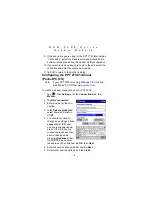
Page 8: ...PT 2700 is running Windows CE OS down load Pocket PC OS from www symbol com To create a modem connection on your PPT 2700 1 Tap then Settings On the Connections tab tap Modem 2 Tap New connection 3 Enter a name for the con nection 4 In the Select a modem list select Powered Serial on COM7 5 You should not need to change any settings in Ad vanced Most ISPs now use a server assigned ad dress If the ...

Page 9: ...Settings Preparing the PPT 2700 for a Modem ActiveSync After you create the connection it appears in Programs Connections To start the connection tap the connection icon enter your user name and password and tap Connect To change connection settings return to Modem Settings Tap the Modem link at the bottom of the Connections folder To return to the Connections folder tap the Connections link ...

Page 10: ... may be used for formatting purposes unless they are embedded in numeric or string constants The termination character may not ap pear in the body The modem can accept at least 40 charac ters in the body Termination character may be selected by a user option parameter S3 The default is CR The format of Basic Syntax commands except for the D and S commands is as follows command number where command...

Page 11: ...cognized as a valid parameter number an ERROR result code issues Immediately following this number either a or character must appear is used to read the current value of the indicated S parameter sets the S parameter to a new value S parameter_number S parameter_number value If the is used the new value to be stored in the S parameter is specified in decimal following the If no value is given i e ...

Page 12: ...ly A D DTMF digits A B C D X L Re dial last number P Pulse dialing X T Tone dialing W Wait for dial tone Modem waits for dial tone be fore dialing digits following W Wait for silence Modem waits for at least 5 sec onds of silence in the call progress frequency band before continuing with next dial string parameter Wait for credit card dialing tone before continuing with the dial string Dial pause ...

Page 13: ...1 On during call establishment Off when receiving carrier default 2 Always on 3 Off when receiving carrier and during dialing On during answering G Guard tone G value X 0 Disables guard tone default 1 Disables guard tone 2 Select 1800 Hz guard tone V1 Displays last connection statistics MS Modulation Selection MS carrier X B103 Bell 103 300 B212 Bell 212 1200 Rx 75 or 75Rx 1200 Tx V21 300 V22 1200...

Page 14: ...ll back Fall forward E value 0 Disable line quality monitor and auto re train 1 Enable line quality monitor and auto re train 2 Enable line quality monitor and fallback fall for ward default B CCITT or Bell B value 0 Select CCITT operation at 300 or 1200 bauds 1 Selects Bell operation at 300 or 1200 bauds L Leased Line Operation L value 0 Requests dial up operation Dial up operation continues Com ...

Page 15: ...3 ASCII S4 Line Feed Character 0 127 10 ASCII S5 Backspace Character 0 255 8 ASCII S6 Wait Time before Blind Dialing or Dial Tone 2 255 2 S S7 Wait Time for Carrier Silence or Dial Tone 1 255 50 S S8 Pause Time for Dial Delay Modifier 0 255 2 S S9 Carrier Detect Response Time 1 255 6 0 1 S S10 Lost Carrier to Hangup Delay 1 255 14 0 1 S S11 DTMF Tone Duration 50 255 95 mS Register value may be sto...

Page 16: ...served 0 S21 V 24 Bit Mapped Options Sta tus 52 34h S22 Speaker Results Bit Mapped Options 117 75h S23 General Bit Mapped Options Status 62 3Dh S24 Sleep Inactivity Timer 0 255 0 S S25 Delay to DTR off 0 255 5 S S26 RTS to CTS Delay 0 255 1 01 S S27 General Bit Mapped Options Status 73 49h Reg Function Range Default Units De fault Saved Register value may be stored in on of two user Country depend...

Page 17: ...APM Failure Control 7 S38 Delay Before Forced Hangup 0 255 20 S S39 Flow Control Bit Mapped Op tions Status 3 S40 General Bit Mapped Options Status 104 68h S41 General Bit Mapped Options Status 195 C3h S46 Data Compression Control 138 S48 V 42 Negotiation Control 7 S86 Call Failure Indication 0 26 0 Reg Function Range Default Units De fault Saved Register value may be stored in on of two user Coun...

Page 18: ...mit Attenuation Level 0 15 10 dBm S92 Fax Transmit Attenuation Lev el 0 15 10 dBm S95 Extended Result Codes Con trol 0 S210 V 34 Symbol Rate 0 255 13 0Dh Reg Function Range Default Units De fault Saved Register value may be stored in on of two user Country dependent ...

Page 19: ...Asynchronous character format Up to 10 bits including data start stop and parity bits Asynchronous data rates Transmission rate fallback through 300 bps Chipset Conexant SCM Compatible public switched network jacks RJ11 Dialing capability Tone and rotary pulse Line requirements Public switched telephone network PSTN including international connections Operating environment Altitude up to 20 000 ft...

Page 20: ...tenna Increase the separation between the equipment and the receiver Connect the equipment into an outlet that is on a circuit different from the receiver Consult the dealer or an experienced radio TV technician for help This device complies with Part 15 of the FCC rules Operation is subject to the following two conditions 1 this device may not cause harmful interference and 2 this device must acc...

Page 21: ...e FCC certification number and Ringer Equivalence Number REN for this equipment If requested this information must be provided to the telephone company The REN is used to determine the quantity of devices that may be connected to the telephone line Excessive devices on the telephone line may result in the devices not ringing in response to an incoming call In most but not all areas the sum of REN ...

Page 22: ...ual The telephone number provided may not be a 900 number or any other number for which charges exceed local or long distance transmission charges In order to program this information into your fax modem consult your fax software user s manual for set up instructions CANADA The Industry Canada label identifies certified equipment This certification means that the equipment meets certain telecommun...

Page 23: ...items will carry a 30 day limited warranty Warranty Coverage and Procedure During the warranty period Symbol will repair or replace defective products returned to Symbol s manufacturing plant in the US For warranty service in North America call the Symbol Support Center at 1 800 653 5350 International customers should contact the local Symbol office or support center If warranty service is require...

Page 24: ...sdictions do not allow the exclusion or limitation of incidental or consequential damages so the proceeding exclusion or limitation may not apply to you Service Information Before you use the unit it must be configured to operate in your facility s network and run your applications If you have a problem running your unit or using your equipment contact your facility s Technical or Systems Support ...

Reviews: