background image

3-53

Setup and Installation: Communication

The Driver Configuration Menu

From the System menu (see 

Figure 3-26 on page 3-26

), press the Previous or Next buttons 

to move the "<" cursor to the Drivers option and press the Enter button. 

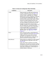
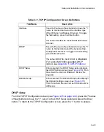
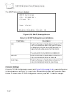
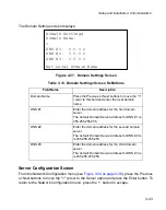
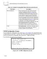
The Driver Configuration menu displays:

Figure 3-44.  Driver Configuration Menu

Table 3-19. Driver Configuration Menu Definitions

Field Name

Description

Internal Scanner

When selected, the Internal Scanner option 
displays the 

Laser Scanner Configuration 

screen 

(see 

Figure 3-45

). For the MK1000’s onboard 

internal laser scanner, the driver can be enabled or 
disabled and the default scan mode can be 
changed. (See 

Appendix C, 

Scanning Mode 

Programming Bar Codes

 for a list of the scan 

modes.) If the driver is disabled then the scanner is 
not initialized and it becomes possible for a user 
application to communicate with the scanner 
directly using the appropriate Com driver (i.e., 
C_SID_IO_UART2).

Driver Configuration

Internal Scanner <
External/Aux Barcode Reader

RS-232 Port

RS-485 Port

KEYPAD: ENABLED

Configure Laser Scanner

Summary of Contents for MicroKiosk MK1000

Page 1: ...MK1000 MicroKiosk Product Reference Guide ...

Page 2: ......

Page 3: ...MK1000 MicroKiosk Product Reference Guide 72 53977 02 Revision A February 2004 ...

Page 4: ... work from a licensed program or use a licensed program in a network without written permission from Symbol The user agrees to maintain Symbol s copyright notice on the licensed programs delivered hereunder and to include the same on any authorized copies it makes in whole or in part The user agrees not to decompile disassemble decode or reverse engineer any licensed program delivered to the user ...

Page 5: ...the MK1000 1 4 Buttons and Controls 1 4 Programmable Function Buttons 1 4 Reset Button 1 4 Contrast Control Button 1 4 Label Message Window 1 5 Bar Code Scanning 1 6 Scanning Modes 1 6 Changing Scanning Modes 1 7 Scanning Guidelines 1 7 Smart Raster 1 8 Scanning Composite 2D Bar Codes 1 9 Specular Reflection 1 10 Using the Display LCD 1 10 Memory 1 10 Flash Memory 1 10 Static Random Access Memory ...

Page 6: ...nnectors Com Scanner Port 2 16 Serial RS 232 Communication 2 16 Undecoded Wand Wand Emulation Communication 2 16 MK1000 LAN Port Pin Outs 2 17 Chapter 3 Setup and Installation Communication Overview 3 1 Communication Protocol Overview 3 2 Communication Interface Overview 3 2 Configuring the MK1000 for Host Communication 3 3 Configuring via the PCK Configuration Menu 3 4 Overview 3 4 MAP PCK Config...

Page 7: ...enu 3 28 Disabling Enabling Function Buttons 3 29 Programming Function Buttons 3 30 Saving Changes 3 30 Entering Alphanumeric Values 3 31 The System Configuration Menu 3 31 System Information Screen 3 34 File Sys DBM Management Screen 3 35 Change Passwords Screen 3 36 Change Unit Settings Screen 3 37 The Network Configuration Menu 3 38 TCP IP Configuration Screen 3 40 Server Configuration Screen 3...

Page 8: ...ransmission 5 5 Example 5 MK1000 Waiting for Host Time out Period 5 6 PCK RS 485 Communication Protocol 5 6 Example 1 Correct Communications No Data 5 7 Example 2 Correct Communications MK1000 Sends Data 5 7 Example 3 Display Message for MK1000 5 7 Default Display Messages 5 8 Powerup Message 5 8 Idle Message Host Connection Failure Message 5 8 Reactivated Host Connection Established Message 5 9 D...

Page 9: ...rogramming Bar Codes Appendix B PCK Configuration Programming Bar Codes Appendix C Scanning Mode Programming Bar Codes Appendix D MK1000 Fonts Appendix E Technical Specifications Appendix F Troubleshooting Appendix G Table of MK1000 Communication Interfaces Appendix H DHCP Options Glossary Index Feedback Quick Startup Instructions ...

Page 10: ...viii MK1000 MicroKiosk Product Reference Guide ...

Page 11: ...cedures parts of the MK1000 features and scanning modes Chapter 2 Setup and Installation Mechanical describes the hardware setup and installation of the MK1000 Chapter 3 Setup and Installation Communication describes the steps required to establish communication between the MK1000 and a host Chapter 4 Software and Applications describes loading applications and files on to the MK1000 Chapter 5 PCK...

Page 12: ...t the communication interfaces supported by the MK1000 Appendix H DHCP Options provides a table with DHCP options supported by the MK1000 Notational Conventions Bullets indicate action items lists of alternatives lists of required steps that are not necessarily sequential Sequential lists e g those that describe step by step procedures appear as numbered lists Related Publications The following is...

Page 13: ...or service information warranty information or technical assistance contact or call the Symbol Support Center in United States Symbol Technologies Inc One Symbol Plaza Holtsville New York 11742 1300 Tel 1 800 653 5350 Canada Symbol Technologies Canada Inc 2540 Matheson Boulevard East Mississauga Ontario Canada L4W 4Z2 Tel 905 629 7226 United Kingdom Symbol Technologies Symbol Place Winnersh Triang...

Page 14: ...talia Symbol Technologies Italia S R L Via Cristoforo Columbo 49 20090 Trezzano S N Navigilo Milano Italy Tel 2 484441 Inside Italy Tel 39 02 484441 Outside Italy Latin America Sales Support 2730 University Dr Coral Springs FL 33065 USA Tel 1 800 347 0178 Inside United States Tel 1 954 255 2610 Outside United States Fax 954 340 9454 Mexico México Symbol Technologies Mexico Ltd Torre Picasso Boulev...

Page 15: ... 5311 Inside South Africa Tel 27 11 809 5311 Outside South Africa Spain España Symbol Technologies S L Avenida de Bruselas 22 Edificio Sauce Alcobendas Madrid 28108 Spain Tel 91 324 40 00 Inside Spain Tel 34 91 324 40 00 Outside Spain Fax 34 91 324 4010 Sweden Sverige Letter address Symbol Technologies AB Box 1354 S 171 26 SOLNA Sweden Visit shipping address Symbol Technologies AB Solna Strandväg ...

Page 16: ...xiv MK1000 MicroKiosk Product Reference Guide ...

Page 17: ...ing and comes complete with the ability to display graphics and text messages to promote seasonal sales in store promotions and upcoming events The programmable function buttons can enhance in store applications and allow for customer interaction Unpacking Your MK1000 Remove the MK1000 from its packing and inspect it for damage If the device was damaged in transit call the Symbol Support Center at...

Page 18: ...eless Power via AC Outlet 1 12 2 4 Wireless Power via Power Over Ethernet 1 12 2 5 RS 485 Installation 2 6 RS 232 Installation 2 9 Mounting 2 11 Cable Pin outs 2 13 2 14 2 15 2 16 Establishing Communication with your Host Selecting a Communicating Interface 3 2 G 1 Methods of Configuring a MK1000 3 3 PCK Configuration Menu 3 2 3 3 3 4 MAP of Menu Structure 3 5 3 7 Entering Navigating and Saving Ch...

Page 19: ...the MK1000 Figure 1 1 Parts of the MK1000 Front View Back View Com Scanner Port Power Port LAN Local Area Network Port Mounting brackets 4 Function Buttons 4 Label Cover Scan Window Reset Button R Contrast Control C Lower Right Side ...

Page 20: ...u on page 3 28 For details on how to enter alphanumeric values while in the System menu see Entering Alphanumeric Values on page 3 31 For details on how to disable and enable function buttons see Disabling Enabling Function Buttons on page 3 29 Reset Button The Reset button shown in Figure 1 1 on page 1 3 can be used to reset the system The Reset button is located on the lower right hand side of t...

Page 21: ...rom one side to bow the label cover then lift off Figure 1 2 Removing the Label Cover To install the plastic label cover 1 Insert the tabs of one end of the label cover into the slots on the front of the MK1000 2 Bow the plastic cover and insert the tabs of the other side of the label cover into the slots on the other end of the MK1000 Press here ...

Page 22: ...directional 1D Scan Pattern factory default This is a highly efficient scan pattern which decodes 1D and EAN UCC reduced space symbologies in any orientation Note While in this mode the MK1000 does not decode 2D bar codes like PDF Always Raster Scan Pattern Directly opens the laser to a full sized raster pattern Decodes 1D PDF 417 RSS and Composite Codes Smart Raster Scan Pattern Creates a single ...

Page 23: ...mming bar code refer to Appendix C Scanning Mode Programming Bar Codes Any changes made by scanning a programming bar code are in effect until the unit is powered off At the unit s next power up the scanner returns to its default scan mode setting Scanning Guidelines When scanning a bar code Keep the scan pattern parallel to the bar code s rows Hold the bar coded item as still as possible Hold the...

Page 24: ...d bottom of a 2D symbol pull the scanner back until it does Make sure the scan pattern extends at least three quarters of an inch beyond the edges of the bar code Figure 1 4 Raster Pattern Expanded Over PDF 417 Symbol If the vertical scan pattern is not high enough to cover a tall PDF 417 symbol move the bar code slowly down toward the bottom of the symbol keeping the beam horizontal to the rows a...

Page 25: ... code Keep the scan pattern parallel to the 2D symbol s rows Hold the bar code as still as possible Hold the bar coded item at an angle which does not cause specular reflection see Specular Reflection on page 1 10 Hold the scanner close for small bar codes and farther away for large bar codes When using the single scan line pattern aim the scan line at the middle of the 2D portion The scan pattern...

Page 26: ... dead zone to avoid 2o from the direct laser beam The specular dead zone is larger for scanning PDF 417 9o from the direct laser beam However the scanner is not effective if its beams hit the bar code s surface at an angle greater than 30o from the normal to that surface Using the Display LCD The MK1000 has a back lit 240 x 64 pixel Liquid Crystal Display LCD The display s colors are white on blue...

Page 27: ...ply plugged into an AC outlet or by Power over Ethernet If an external power supply is used it plugs into the power port on the rear of the MK1000 via a 2 0mm barrel jack The center pin of the jack is positive and the outer tab is ground The universal power supply provided with your MK1000 is compatible with the following power systems 120V 60Hz North America 230V 50Hz International excluding Japa...

Page 28: ...lation the MK1000 receives power via the power supply plugged into an AC outlet Wired Ethernet Power via Power over Ethernet The MK1000 supports Power over Ethernet Symbol Technologies Bias T functionality When an Ethernet 10Base T cable is connected to the LAN port in addition to being the conduit for data exchange it can also be used as a conduit to provide power to the MK1000 RS 485 RS 485 is s...

Page 29: ...quired for the following four MK1000 communication interfaces Wireless Ethernet 2Mb or 11Mb RF Power via AC outlet Power via Power over Ethernet Wired Ethernet 10Base T cable Power via AC outlet Power via Power over Ethernet Wired RS 485 Serial cable Wired RS 232 Serial cable Note After completing the mechanical installation of the MK1000 refer to Chapter 3 Setup and Installation Communication to ...

Page 30: ...e power to the MK1000 using its power supply Insert the round barrel connector at the end of the power supply cable into the MK1000 s Power port See Figure 1 1 on page 1 3 for port locations Plug the power supply into a wall outlet 2 Attach the Ethernet cable Connect the Ethernet cable to the LAN port on the MK1000 See Figure 1 1 on page 1 3 for port locations Ensure the Ethernet cable is terminat...

Page 31: ...structions below 1 Attach the Ethernet cable Connect the Ethernet cable to the LAN port on the MK1000 See Figure 1 1 on page 1 3 for port locations Ensure the Ethernet cable is terminated according to the Ethernet Pin Outs Obtaining Power via Power over Ethernet described in Table 2 3 and Table 2 4 Plug the other end of the Ethernet cable into the Bias T Power over Ethernet module 2 Connect a patc...

Page 32: ...to the host via a wireless RF connection and receives power via a power supply plugged into an AC outlet To install the MK1000 follow the instructions below 1 Provide power to the MK1000 using its power supply Insert the round barrel connector at the end of the power supply cable into the MK1000 s Power port See Figure 1 1 on page 1 3 for port locations Plug the power supply into a wall outlet 2 T...

Page 33: ...Ethernet cable to the LAN port on the MK1000 See Figure 1 1 on page 1 3 for port locations Ensure the Ethernet cable is terminated according to the Ethernet Pin Outs Obtaining Power via Power over Ethernet described in Table 2 3 and Table 2 4 Plug the other end of the Ethernet cable in the hub 2 Connect a patch cable from the Bias T Power over Ethernet module to your host system s LAN port 3 To mo...

Page 34: ...al When installing an RS 485 configuration ensure each MK1000 is connected directly to the RS 485 bus see Figure 2 1 Figure 2 1 Connector Block The cable required for an RS 485 installation should meet or exceed the following specifications 1 twisted pair 26 AWG 7 34 tinned copper twisted pair foil wrapped 100 coverage nominal impedance 120 ohms capacitance between twisted pair 10 25 pf per foot c...

Page 35: ...the conversion box to the host using an RS 232 cable 3 Attach the RS 485 Serial cable Connect the RS 485 Serial cable to the LAN port on the MK1000 See Figure 1 1 on page 1 3 for port locations Ensure the Serial cable is terminated according to the RS 485 Connectors LAN Port described in Table 2 5 Plug the other end of the RS 485 Serial cable into the converter box 4 To mount the MK1000 see Mounti...

Page 36: ...2 W 100Ω 100Ω Rt GW 1 2 W 1 2 W 100Ω 100Ω 4000 Ft Maximum Termination Resistors at Both Ends RS 232 RS 485 Conversion Box Rt 1 2 3 4 1 2 3 4 GWG GWG 100Ω 100Ω 100Ω 100Ω 1 2 W GWG Green wire ground or power system ground Circuit ground or circuit common Rt 120Ω 1 2W Recommended RS 485 Two Wire Multidrop NetWork ...

Page 37: ...rt See Figure 1 1 on page 1 3 for port locations Plug the power supply into a wall outlet 2 Attach the RS 232 Serial cable Connect the RS 232 Serial cable to the Com Scanner port on the MK1000 See Figure 1 1 on page 1 3 for port locations Ensure the Serial cable is terminated according to the Serial RS 232 Communication pin outs described in Table 2 6 Plug the other end of the Serial cable into th...

Page 38: ...ow the instructions below 1 Attach the auxiliary device s cable to the Com Scanner port on the MK1000 See Figure 1 1 on page 1 3 for port locations Ensure the auxiliary device s cable is terminated properly For Serial RS 232 Communication pin outs see Table 2 6 For Undecoded Wand Wand Emulation Communication pin outs see Table 2 7 2 Plug the other end of the cable into the auxiliary device 3 To mo...

Page 39: ...e wall mount kit follow the instructions below 1 Determine the MK1000 mounting location 2 Using a pencil mark the mounting screw location Refer to the mounting template provided in the MK1000 Quick Reference Guide p n 72 52968 xx included with every MK1000 The screws must be 5 inches 12 7 cm apart left to right and 6 inches 15 3 cm apart top to bottom Figure 2 3 Mounting Dimensions There must be a...

Page 40: ...ck of the MK1000 to slide onto Ensure the screws are securely an chored to the wall 2 Place the MK1000 on the wall aligning the notches on the back of the unit with the mounting screws Ensure all cables lie neatly in the channel provided on the back of the unit 3 Slide the MK1000 to the left and down to secure in place Figure 2 4 Mounting Directions ...

Page 41: ...e MK1000 Figure 2 5 8 Pin and 10 Pin Connectors Ethernet Connectors LAN Port Ethernet Pin Outs Obtaining Power via AC Power Supply Table 2 1 Ethernet 10Base T Cable 8 Pin Pin Description Pin 1 TXD Pin 2 TXD Pin 3 RXD Pin 6 RXD Pin 7 GND Pin 8 GND Table 2 2 Ethernet 10Base T Cable 10 Pin Pin Description Pin 2 TXD Pin 3 TXD Pin 1 Pin 8 Pin 1 Pin 10 8 Pin 10 Pin ...

Page 42: ...the MK1000 through a single Ethernet cable If power to the MK1000 is being provided via Power over Ethernet do NOT plug the power supply into the MK1000 as well Pin 4 RXD Pin 7 RXD Pin 8 GND Pin 9 GND Table 2 3 Power over Ethernet Cable 8 Pin Pin Description Pin 1 TXD Pin 2 TXD Pin 3 RXD Pin 4 Bias T Pin 5 Bias T Pin 6 RXD Pin 7 GND Pin 8 GND Table 2 2 Ethernet 10Base T Cable 10 Pin Continued Pin ...

Page 43: ...rs LAN Port Table 2 4 Power over Ethernet Cable 10 Pin Pin Description Pin 2 TXD Pin 3 TXD Pin 4 RXD Pin 5 Bias T Pin 6 Bias T Pin 7 RXD Pin 8 GND Pin 9 GND Table 2 5 RS 485 Cable 10 Pin Pin Description Pin 1 RS 485 Pin 8 GND Pin 10 RS 485 Inverted Signal ...

Page 44: ...ween an external hand held decoded scanner and the MK1000 Undecoded Wand Wand Emulation Communication Table 2 6 RS 232 Cable 10 Pin Pin Description Pin 1 5V 500mA maximum output Pin 3 RXD input Pin 5 RTS output Pin 6 Ground Pin 7 CTS input Pin 9 TXD output Table 2 7 Undecoded Auxiliary Device Cable 10 Pin Pin Description Pin 1 Power 5V 200mA maximum Pin 2 Laser On Pin 4 DBP Pin 6 GND Pin 8 Trigger...

Page 45: ...ven for general starting information only To generate a cable to attach to the MK1000 see Cable Pin Outs on page 2 13 Table 2 8 MK1000 LAN Port RJ 45 10 Pin Pin Description Pin 1 RS 485 TXD RXD Pin 2 10BaseT TXD Pin 3 10BaseT TXD Pin 4 10BaseT RXD Pin 5 BIAS T Pin 6 BIAS T Pin 7 10BaseT RXD Pin 8 GND Pin 9 GND Pin 10 RS 485 TXD RXD ...

Page 46: ...2 18 MK1000 MicroKiosk Product Reference Guide ...

Page 47: ...ms that support these interfaces include Windows Unix DOS and IBM 468x 469x Topics covered in this chapter include Communication protocol PCK emulation overview Selecting a communication interface Configuring for host communication via the System menu Configuring for host communication via the PCK Configuration menu Configuring for host communication via a Telnet client Before communications with ...

Page 48: ...te The MK1000 s PCK emulation application is not compatible with pre existing PCK9142 9144 9130 applications Communication Interface Overview Before establishing communications with the host you must determine which communication interface to use Your MK1000 may support up to four communication interfaces The four types of interfaces are listed in Table 3 1 The number and type of communication int...

Page 49: ...on Key ID and Key Management These parameters can be configured from the System menu and or a Telnet Session 2 Telnet sessions require an Ethernet connection between the host and the MK1000 3 PCK Configuration programming bar codes are located in Appendix B PCK Configuration Programming Bar Codes 4 System menu programming bar codes are available in Appendix A Configuration Menu Programming Bar Cod...

Page 50: ...u can be accessed locally by scanning programming barcodes which are available in Appendix B PCK Configuration Programming Bar Codes From the PCK Configuration menu all MK1000 parameters can be accessed except the RF Settings ESS ID Encryption Key ID and Key Management These parameters can only be accessed from the System menu and or a Telnet session For information on alternate methods of configu...

Page 51: ...5 Setup and Installation Communication MAP PCK Configuration Menu The following map can be used to assist in the navigation of the PCK application Figure 3 1 Navigating the PCK Configuration Menus Screens ...

Page 52: ...e Main Menu To navigate the main menu scan the numeric programming bar code in Appendix B PCK Configuration Programming Bar Codes that corresponds to the menu option parameter you wish to review change For example if you wish to change host parameters you can access the Select Host Params screen by scanning the 2 bar code at the PCK Configuration menu Saving Changes After making your desired chang...

Page 53: ...es that corresponds to the parameter you wish to select For example to change the communication interface to wired Ethernet navigate the main menu and make your communication interface selection as follows 1 Scan the Enter PCK Configuration Menu bar code to access the PCK Configuration menu 2 Scan the number 1 bar code to access the Select Interface Type screen 3 Scan the number 1 bar code to choo...

Page 54: ...e the MK1000 s IP address by scanning the number 3 bar code Change Host Config at the PCK Configuration menu to access the TCP IP Configuration Page 1 4 Scan the number 1 bar code TCP IP to access TCP IP Configuration Page 1 screen 5 Scan the number 2 bar code IP Address to access the IP address data field This screen displays the current IP address field Curr IP Addr and the new IP address field ...

Page 55: ... programming bar codes in this order Scan Bar Code Screen Display 2 2 3 23 4 234 2 234 2 3 234 23 9 234 239 0 234 239 0 0 234 239 00 5 234 239 005 0 234 239 005 0 1 234 239 005 01 6 234 239 005 016 Save Exit Previous screen I P address changed Save Exit Main menu Save Exit Exit main menu and initiate operation of the MK1000 in PCK emulation mode ...

Page 56: ... or change the interface type that the MK1000 uses to talk to a host choose Change Interface at the PCK Configuration menu by scanning the 1 bar code located in the section Numeric Bar Codes on page B 7 The Select Interface Type screen displays Figure 3 3 Select Interface Type Screen Scanning a 1 or 2 bar code sets the type Wired 10BaseT or Wireless and returns you to the PCK Configuration menu Se...

Page 57: ... 4 bar code displays the appropriate screen to select or change host parameters Scan the 1 bar code to select or change the host type Scan the 2 bar code to edit Software Handshaking Scan the 3 bar code to change the host time out period Scan the 4 bar code to change host Turnaround Time Note When returned to this menu after making changes on any of the Host Params sub screens you must scan the Sa...

Page 58: ... Params menu scan the Save Exit bar code to save changes and exit Editing Software Handshaking Note Software Handshaking configuration supported in PCK emulation versions 1 06 and greater When you scan the 2 bar code at the Select Host Params menu the Software Handshaking Config screen displays Figure 3 6 Software Handshaking Config Screen Select Host Type 1 TCP IP 2 UDP IP 3 RS 232 4 RS 485 Scan ...

Page 59: ...period The time out period determines the maximum time allowed to elapse before the MK1000 assumes end of transmission The delay period can range from 0 1 to 9 9 seconds in 1 second increments After scanning the appropriate host time out period scan the Save Exit bar code on page B 4 to save the changes and return to the Select Host Params menu Editing Host Turnaround Time When you scan the 4 bar ...

Page 60: ...selected If it is inappropriate scan the Cancel bar code to return to the main PCK Configuration menu and scan the 2 bar code Change Host Type to set the correct host type The host configuration screen displayed can be a Serial type RS 232 or RS 485 or an Ethernet host If an Ethernet host either a TCP IP configuration or UDP IP configuration screen displays Ensure this setting is correct If not co...

Page 61: ... code to display the respective screen Scan the number 3 to return to the previous screen Editing IP Address When IP Address is selected at the TCP IP Configuration Page1 screen the following screen displays Figure 3 11 IP Address Screen To enter changes on this screen scan the required numeric bar code s to enter data in the New IP Addr field as necessary For Host IP addresses you must enter thre...

Page 62: ...screen scan the required numeric bar code s to enter data in the New Subnet Mask field as necessary You must enter three digits for each segment for dots to be supplied correctly For example if you want to set the address 10 10 1 2 you must enter 010 010 001 002 Remember to scan the Save Exit bar code when you are finished or scan Cancel to escape WITHOUT completing the entry Note You must scan Ca...

Page 63: ...10 001 002 Remember to scan the Save Exit bar code when you are finished or scan Cancel to escape WITHOUT completing the entry Note You must scan Cancel two times to escape WITHOUT completing the entry The first scan erases the data and the second scan escapes to the previous screen WITHOUT completing the entry Editing DNS Domain Settings Configuration When Go To DNS Screen is selected at the TCP ...

Page 64: ... segment for dots to be supplied correctly For example if you want to set the address 10 10 1 2 you must enter 010 010 001 002 Remember to scan the Save Exit bar code when you are finished or scan Cancel to escape WITHOUT completing the entry Note You must scan Cancel two times to escape WITHOUT completing the entry The first scan erases the data and the second scan escapes to the previous screen ...

Page 65: ...ting the entry The first scan erases the data and the second scan escapes to the previous screen WITHOUT completing the entry Editing Host Port When Host Port is selected at the TCP IP Configuration Page 2 screen the following screen displays Figure 3 17 Host Port Screen To enter changes on this screen scan the required numeric bar code s to enter data in the New Srvr Port field as necessary Remem...

Page 66: ...s see Appendix H DHCP Options To change the IP Address Subnet Mask Gateway or DNS configuration scan the number 2 3 4 or 5 bar code to display the respective screen Scan the number 6 bar code to display the second UDP IP screen Figure 3 19 UDP IP Configuration Page 2 To change the Server Host IP or Server Host Port scan the number 1 or 2 bar code to display the respective screen Scan the number 3 ...

Page 67: ...g the entry RS 232 RS 485 Configuration When Change Host Config is selected at the PCK Configuration menu the system automatically displays the current host type If RS 232 or RS 485 is the current host type the appropriate screen displays for configuration Refer to the section Auxiliary Port Parameters for RS 232 and RS 485 configuration information Auxiliary Port Parameters Edit Aux Port Params P...

Page 68: ...f you wish to exit any screen without completing your entries scan the Cancel bar code to return to the parent screen Any changes made in the present screen are discarded Selecting a Baud When Baud is selected at the RS 232 RS 485 Configuration screen by scanning the 1 bar code located in the section Numeric Bar Codes beginning on page B 6 the following screen displays Figure 3 21 Baud Rate Screen...

Page 69: ...e when you are finished or scan Cancel to escape WITHOUT completing the entry Selecting Stopbits When Stop Bits is selected at the RS 232 RS 485 Configuration screen by scanning the 3 bar code located in the section Numeric Bar Codes beginning on page B 6 the following screen displays Figure 3 23 Stopbits Screen Scan the required numeric bar code s to enter the new stopbits value Remember to scan ...

Page 70: ...leting the entry Selecting Flow Control When Flow Cntrl is selected at the RS 232 RS 485 Configuration screen by scanning the 5 bar code located in the section Numeric Bar Codes beginning on page B 6 the following screen displays Figure 3 25 Flow Control Screen Scan the required numeric bar code s to select the new flow control Remember to scan the Save Exit bar code when you are finished or scan ...

Page 71: ...d for configuring the unit The System menu can be accessed locally using the MK1000 function buttons locally by scanning programming bar codes or remotely via a Telnet client From the System menu all MK1000 parameters can be accessed except the PCK communication interface Change Select Host Type software handshaking and RS 485 Net ID These parameters can only be accessed from the PCK Configuration...

Page 72: ...3 26 MK1000 MicroKiosk Product Reference Guide MAP System Menu Upon entering the menu system Figure 3 26 is used for navigation Figure 3 26 System Menus Screens ...

Page 73: ...reens remotely via Telnet refer to Configuration via a Telnet Session on page 3 63 To use the MK1000 function buttons to access the first configuration menu 1 Press the 1 and 4 buttons simultaneously to display the Password screen Figure 3 27 Password Screen 2 Using the four function buttons enter the password 44213 Note If you enter the wrong 5 digit password the system returns to the Out of Serv...

Page 74: ...ystem automatically terminates and resumes the application process es that was were previously active Navigating the System Menu The MK1000 has four function buttons located on the front panel See Parts of the MK1000 on page 1 3 for button locations These buttons can be used to navigate the configuration menu and configure system parameters Note In addition to the four function buttons the bar cod...

Page 75: ...bled the keypad can be restored either through a Telnet session and accessing the Drivers menu or by pressing and holding the 4 button while the unit is booting up Table 3 3 Navigating The Configuration Menus Screens Using Function Buttons Button Button Use Description Button 1 Escape Returns to the previous screen Button 2 Previous Moves the cursor designated by the symbol up to any selectable me...

Page 76: ...reens messages for each of those events Also see Table 5 4 on page 5 10 for information about Command Parameters All other messages screens are host driven including scanner and button responses The developer should be able to track what is displayed because the host application drives the screen content Saving Changes Exiting the System menu via the Save Reboot option saves any changes made Chang...

Page 77: ... Previous and Next buttons to rotate through all possible values 0 9 4 When you reach the desired value press the Enter button to lock it in and move to the next position 5 If the desired value is entered into a position and you are finished data entry press the Escape button to leave scroll edit mode 6 Press Enter to make the change permanent The cursor points to the field you just changed 7 Pres...

Page 78: ...ement screen see Figure 3 31 From this screen it is possible to delete files located in RAM or delete database memory which constitutes user stored values in the system DBM or GL Deleting the database also returns all driver configuration settings to their defaults Passwords When selected the Passwords option displays the Change Passwords screen see Figure 3 32 From this screen you can set and cha...

Page 79: ... used by the user s application for any other purpose The default Debug Mode for the MK1000 is DISABLED Embedded Apps Toggle this field by pressing the Enter button Enabling Embedded Apps allows the PCK emulation to run or if configured the built in Demo and Factory Test programs Disabling Embedded Apps allows a downloaded user application to operate without interference from any application progr...

Page 80: ...ption Boot P N This field represents the CTC boot block part number The default Boot P N for the MK1000 is S 14 00D 0N 09 Boot Vers The MK1000 boot block version number is V01 12 09 OS P N This field represents the CTC operating system part number The default OS P N for the MK1000 is S 14 001 11 0Fx OS Vers The MK1000 OS firmware version number is V4 06 08 APP P N This field represents the embedde...

Page 81: ...PP Vers The PCK application version number Table 3 7 File Sys DBM Management Screen Definitions Field Name Description Delete Files When this option is selected all files in RAM are deleted and the MK1000 reboots This option must be executed before loading new firmware OS if an upgraded version of the PCK emulation application was loaded Delete Database When this option is selected the database of...

Page 82: ...ape The Change Passwords screen displays Figure 3 32 Change Passwords Screen Table 3 8 Change Passwords Screen Definitions Field Name Description FTP Telnet Password Press the Previous or Next buttons to move the cursor to this field and enter the password required for FTP Telnet operation Keypad Password Press the Previous or Next buttons to move the cursor to this field and enter the password re...

Page 83: ...ss the Enter button To return to the System Configuration menu press the 1 button to escape The Unit Settings screen displays Figure 3 33 Unit Settings Screen Table 3 9 Unit Settings Screen Definitions Field Name Description Serial This is a read only field that includes the unit s serial number Unit ID This is a read only field that includes an identification number for the unit Serial 01289AL051...

Page 84: ...4 Network Configuration Menu Note If DHCP mode is disabled and the IP address for either Wired Ethernet or Wireless Ethernet is set to 0 0 0 0 all zeros then that interface attempts a BOOTP operation to obtain its IP address Netmask and Gateway IP Once a DHCP or BOOTP operation is successfully performed the appropriate fields for the requesting device are filled in with the obtained values Network...

Page 85: ... is necessary to ensure that the two interfaces are not setup on the same subnet Configuring DHCP mode enables DHCP upon startup for either or both interfaces if enabled For a list of MK1000 supported DHCP options see Appendix H DHCP Options Server When selected the Server option displays the Server Configuration screen see Figure 3 38 The fields on this screen can be used to provide information t...

Page 86: ... nearly identical in function to that of the Wired Ethernet port The MAC address of the radio if present is displayed at the top of the configuration screen also factory assigned Also on this screen is a link to RF Settings see Figure 3 41 that allows configuration of Wireless Ethernet specific parameters such as ESS ID Encryption type Key ID and Key Management From the Key Management screen it is...

Page 87: ...o toggle the field setting press the Enter button The default Interface for the MK1000 is Wireless Ethernet DHCP Press the Previous or Next buttons to move the cursor to this field and select the Dynamic Host Configuration Protocol To toggle the field setting press the Enter button The default DHCP for the MK1000 is DISABLED For a list of MK1000 supported DHCP options see Appendix H DHCP Options D...

Page 88: ...3 12 DHCP Settings Screen Definitions Field Name Description CID Press the Previous or Next buttons to move the cursor to this field and select the option to enable or disable the Client ID see Client ID below To toggle the field setting press the Enter button The default CID for the MK1000 is DISABLED Client ID Press the Previous or Next buttons to move the cursor to this field and enter the Clie...

Page 89: ...en Definitions Field Name Description Domain Name Press the Previous or Next buttons to move the cursor to this field and enter the local domain name DNS 1 Enter the domain address for the first domain server The default Domain Server address for DNS 1 is 255 255 255 255 DNS 2 Enter the domain address for the second domain server The default Domain Server address for DNS 2 is is 255 255 255 255 DN...

Page 90: ... to escape Table 3 14 Server Configuration Screen Definitions Field Name Description Server IP Press the Previous or Next buttons to move the cursor to this field and enter the Server IP address The default Server IP address for the MK1000 is 192 168 1 1 Server Port Press the Previous or Next buttons to move the cursor to this field and enter the Server port The default Server Port for the MK1000 ...

Page 91: ... button To return to the Network Configuration menu press the 1 button to escape The Wireless Ethernet Config screen displays Figure 3 40 Wireless Ethernet Config Screen Wired Ethernet Configuration MAC Address 00 60 A3 00 00 05 Enabled Yes IP Address 192 168 0 1 Netmask IP 255 255 255 0 Gateway IP 255 255 255 255 Enable Disable Wired Ethernet Wireless Ethernet Config MAC Address 00 A0 F8 33 5D C6...

Page 92: ...tting press the Enter button IP Address Press the Previous or Next buttons to move the cursor to this field to modify the IP address associated with this port The default Wired Ethernet IP address for the MK1000 is 192 168 0 1 The default wireless Ethernet IP address for the MK1000 is 192 168 0 2 Netmask IP Press the Previous or Next buttons to move the cursor to this field to modify the Netmask I...

Page 93: ...iguration menu press the 1 button to escape The RF Network Settings screen displays Figure 3 41 Wireless Ethernet Config RF Network Settings Screen RF Settings Wireless Ethernet only When selected at the Wireless Ethernet Config screen the RF Settings option displays the RF Network Settings screen see Figure 3 41 From this screen the user can configure radio specific parameters such as ESS ID Encr...

Page 94: ...cryption mode The default encryption mode for the MK1000 is Disabled To toggle the field setting to select OPEN KEY 40 BIT or 128 BIT modes press the Enter button Key ID Press the Previous or Next buttons to move the cursor to this field to set the active key The default active Key ID for the MK1000 is key button 1 To toggle the field setting to select key 2 3 or 4 press the Enter button Key Manag...

Page 95: ...1000 was powered up with these two options already set If these options were not set the values displayed are all zeroes Figure 3 42 shows the values of inactive Radio Status screen To return to the RF Network Setting screen press the 1 button to escape Table 3 17 Radio Status Screen Definitions Field Name Description Note All fields on this screen are read only RF Mac This field includes the MAC ...

Page 96: ...K1000 the value in this field is Down This field is read only Chan This field includes the radio channel ID selected by the AP for RF communications This value is usually 11 If the TCP IP interface is not set to Wireless Ethernet and the Wireless Ethernet Configuration is not set to Enabled prior to powering up the MK1000 the value in this field is 0 This field is read only TxRate This field inclu...

Page 97: ...n is not set to Enabled prior to powering up the MK1000 the value in this field is 0 This field is read only ASL Average Signal Level This field includes the RF signal quality The higher the value the better the signal quality If the TCP IP interface is not set to Wireless Ethernet and the Wireless Ethernet Configuration is not set to Enabled prior to powering up the MK1000 the value in this field...

Page 98: ... TFTP Configuration Screen Table 3 18 TFTP Configuration Screen Definitions Field Name Description TFTP IP Press the Previous or Next buttons to move the cursor to this field to enter the TFTP IP address The default TFTP IP address for the MK1000 is no address all zeros TFTP Server Press the Previous or Next buttons to move the cursor to this field to enter the TFTP server name File Name Press the...

Page 99: ...l Scanner option displays the Laser Scanner Configuration screen see Figure 3 45 For the MK1000 s onboard internal laser scanner the driver can be enabled or disabled and the default scan mode can be changed See Appendix C Scanning Mode Programming Bar Codes for a list of the scan modes If the driver is disabled then the scanner is not initialized and it becomes possible for a user application to ...

Page 100: ...e RS 485 Port option displays the RS 485 Configuration screen see Figure 3 47 The RS 485 screen is the same in structure as the RS 232 screen above The main difference is in the available number of Data Bits as well as extra modes in the Rx Mode configuration option Hardware support exists for both 10 bit and 11 bit serial frames start bit data bits parity stop bits only KEYPAD When selected the K...

Page 101: ... this field and toggle by pressing the Enter button to enable or disable the scanner driver If the driver is disabled then the scanner is not initialized and it becomes possible for a user application to communicate with the scanner directly using the appropriate Com driver i e C_SID_IO_UART2 The default laser scanner driver setting for the MK1000 is ENABLED Scan Mode Press the Previous or Next bu...

Page 102: ...aracter field that is used for custom scanner parameter settings These parameter settings conform to the option codes and values defined in the SE 2223 3223 Integration Guide p n 70 36636 xx Multiple codes and values may be entered but all values must be in hexadecimal format For example to cause all decoded bar codes to be terminated with a carriage return line feed character pair the following s...

Page 103: ...Description Baud Rate Press the Previous or Next buttons to move the cursor to this field and toggle by pressing the Enter button to select the Baud Rate The default Baud Rate for MK1000 RS 232 port settings is 9600 Available Baud Rates 110 300 600 1200 2400 4800 9600 14400 19200 or 38400 Parity Press the Previous or Next buttons to move the cursor to this field and toggle by pressing the Enter bu...

Page 104: ...s to move the cursor to this field and toggle by pressing the Enter button to select the Flow Control The default Flow Control setting for MK1000 RS 232 port settings is DTR DSR Available Flow Control settings DTR DSR BUSY NONE or XON OFF Echo Mode Press the Previous or Next buttons to move the cursor to this field and toggle by pressing the Enter button to select the Echo Mode The default Echo Mo...

Page 105: ...itions as the RS 232 Config screen with a slight difference RS 485 includes extra Rx modes and hardware support exists for 10 bit and 11 bit serial frames start bit data bits parity stop bits only Table 3 22 RS 485 Config Screen Definitions Field Name Description Baud Rate Press the Previous or Next buttons to move the cursor to this field and toggle by pressing the Enter button to select the Baud...

Page 106: ... to this field and toggle by pressing the Enter button to select the Stop Bits The default Stop Bits setting for MK1000 RS 485 port settings is 1 BIT Available Stop Bits settings 1 BIT or 2 BITS Flow Control Press the Previous or Next buttons to move the cursor to this field and toggle by pressing the Enter button to select the Flow Control The default Flow Control setting for MK1000 RS 485 port s...

Page 107: ... press the Enter button The User Configuration menu displays Figure 3 48 User Configuration Menu Rx Mode Press the Previous or Next buttons to move the cursor to this field and toggle by pressing the Enter button to select the Rx Mode The default Rx Mode setting for MK1000 RS 485 port settings is XPT Available Rx Mode settings PRTR CMDL or XPT Table 3 22 RS 485 Config Screen Definitions Continued ...

Page 108: ...can range from 100 to 9900 msecs in 100 msec increments The default Host Time out period is 2000 msecs Turnaround Time Press the Previous or Next buttons to move the cursor to this field and enter the Turnaround Time The turnaround time is the time period that the host or MK1000 waits before sending a response The turnaround time can range from 5 to 255 msecs The default Turnaround Time for the MK...

Page 109: ...ion From the System menu all MK1000 parameters can be accessed except the PCK communication interface Change Select Host Type software handshaking and RS 485 Net ID These parameters can only be accessed from the PCK Configuration menu For information on alternate methods of configuring the MK1000 see page 3 3 MAP Telnet Menu Upon initiating the Telnet session screens appear as they do when navigat...

Page 110: ...troubleshooting section Next you may be asked to ENTER PASSWORD Type in 44213 and press Enter Note while typing in the password the cursor remains stationary while continuing to blink Some Telnet clients may require a simultaneous Ctrl Enter Navigating the Telnet Menu To navigate within the Telnet session use the following buttons Table 3 24 Telnet Navigation Buttons Button Description Moves the c...

Page 111: ...I terminal emulation If running a Telnet session from a laptop you may need to turn off the Num Lock key Saving Changes and Exiting the Telnet Session After you have navigated through the necessary screens and made your desired changes you can save these changes by highlighting the Save Reboot option from the System menu and then pressing the Enter key ...

Page 112: ...3 66 MK1000 MicroKiosk Product Reference Guide ...

Page 113: ...here is a desire is to demonstrate the basic functionality of the MK1000 without connecting to a network and host Several aspects of the MK1000 can be demonstrated including button functions and bar code lookups Button 1 puts the scanner into smart raster mode for reading PDF and composite codes Button 2 puts the scanner into 1 Dimension bar code omni direction decode mode Buttons 3 and 4 displays...

Page 114: ...roKiosk Product Reference Guide Entering Exiting Demo Mode With the communication protocol set to PCK emulation application scan the Enter Exit Demo Mode bar code below to enter or exit demo mode Enter Exit Demo Mode ...

Page 115: ...4 3 Software and Applications While in demo mode scan a demonstration bar code below to emulate a product look up Vitamin C Tablets French Halls Cough Drops Spanish Aspirin English ...

Page 116: ...4 4 MK1000 MicroKiosk Product Reference Guide ...

Page 117: ...ogies for use with its Kiosk Scanning Solutions While running this application the MK1000 can interact with PCK9100 9140 compatible applications on the host It receives commands and data from the host and displays them on the MK1000 s screen The PCK emulation application has operating parameters that can be modified by the user The user can set these parameters using menu screens displayed on the ...

Page 118: ...K Emulation PCK9100 9140 Architecture The MK1000 s operating system supports multiple communication interfaces Wireless RF cabled Ethernet RS 485 and RS 232 co existing on a single unit The PCK9100 9140 was one interface per unit The MK1000 can be configured via a PC file that can be FTPed to the unit The PCK9100 9140 could not The MK1000 has four programmable function buttons The PCK9100 9140 did...

Page 119: ...CII Start of Text ETX 03 ASCII End of Text SOH 01 ASCII Start of Header EOT 04 ASCII End of Transmission DATA 00 FF Data packet This is the actual data being sent to the MK1000 The maximum size of the packet is 300 bytes but under 50 is recommended for accurate communication LRC 00 FF Used for error detection LRC is the Exclusive OR XOR of all characters in DATA and the ETX ADDR 30 4F The address ...

Page 120: ... Time after the last character is received before transmitting back to the host None The MK1000 transmits data to the host without software handshaking and assumes an ACK The EOT character is sent immediately after the LRC Host handshaking is ignored ACK NAK ACK NAK is the default software handshaking The host verifies the LRC and responds with an ACK or NAK If no response is received within the H...

Page 121: ...racters Communications Examples Example 1 Correct Communications Example 2 Wrong First Transmission Example 3 No Time out Example 4 Host Not Receiving Transmission MK1000 Host STX DATA ETX LRC ACK EOT MK1000 Host STX DATA ETX LRC NAK No Time out MK1000 Host STX DATA ETX LRC ACK EOT MK1000 Host STX DATA ETX LRC No response ...

Page 122: ...ddress programmable by bar code menus The value of the address ranges from hex 30 48 decimal to hex 4F 79 decimal The poll command format is EOT ADDR ENQ The host and the MK1000 communicate with each other using the following packet format SOH ADDR STX DATA ETX LRC If the MK1000 is polled and has no data it responds with an EOT character The same ACK NAK protocol used for RS 232 is used for RS 485...

Page 123: ...munications No Data Example 2 Correct Communications MK1000 Sends Data Example 3 Display Message for MK1000 Host MK1000 EOT ADDR ENQ EOT Host MK1000 EOT ADDR ENQ SOH ADDR STX DATA ETX LRC ACK EOT Host MK1000 SOH ADDR STX DATA ETX LRC ACK EOT ...

Page 124: ... host commands are lost when the unit is powered down and must be resent when the unit is powered up again Powerup Message This default message displays when the unit powers up Figure 5 1 Powerup Default Message Idle Message Host Connection Failure Message This default message displays if the MK1000 is not polled by the host for more than one minute or if a connection fails to the host Figure 5 2 ...

Page 125: ...ze of the currently selected font Table 5 3 Display Control Characters Control Character Hex Representation Function VT 0BH Clear display go to top left position FF 0CH Clear display go to top left position CR 0DH Go to left most position of next line SO 0EH Shift Out Set the shift state that causes the most significant bit of all subsequent characters to be flipped This allows 7 bit systems to ac...

Page 126: ...e is 0 239 Py Y axis parameter specified with ASCII digits Valid range is 0 63 Pf Fill No Fill flag parameter used to fill graphic geometric shapes No Fill 0 Fill 1 Pi ID parameter that specifies a particular bitmap font or message ID numbers are assigned through the Resource Manager program Any valid ID number may identify a bitmap font message Valid ranges are Bitmaps 0 999 Fonts 0 1000 where 10...

Page 127: ... 1 the rectangle is filled If Pf 0 it is not filled ESC Px1 Py1 Px2 Py2 PfR ESC 10 10 100 40 1R draws a filled rectangle from 10 10 to 100 40 in the current color Note If any corner is off the screen the rectangle is not drawn Set Color Sets the drawing color for subsequent graphics commands ESC 30m sets the color to black ESC 37m sets the color to white N A Draw Bitmap Draws the bitmap specified ...

Page 128: ... of the font height Set Text Drawing Mode Sets the drawing mode for subsequent text output commands When Pm 0 any text output overlays the current image when Pm 1 it is XORed with the current image ESC PmM Position Cursor Positions text cursor to a specified point on the display characters are drawn with the left side of the character cell at the X cursor position and the character baseline at the...

Page 129: ...any messages from Resource files with the same ID Messages in RAM or from Resource files override default messages Be sure messages do not call each other recursively A message called from another is not displayed until the first message is done Approximately 10 messages waiting to be displayed can be stored Commands from the host are also stored Store Message ESC PiK Message Text The MK1000 store...

Page 130: ...ion FF 0C Command Syntax Optional text font or position command e g xy coordinates to position a message Data message etx 03 lrc Exclusive or of all characters transmitted except for the stx character calculated longitudinal redundancy check Command Syntax Examples Table 5 8 Clear Screen 02 0C 03 0F stx FF etx lrc Table 5 9 Send Text esc 1 1 T Table 5 10 Position Cursor Then Send Text esc Px Py T ...

Page 131: ...end HI 02 0C 1B 5B 31 3B 31 54 48 49 03 21 stx FF esc 1 1 T H I etx lrc Table 5 13 Clear Screen Send HI at Position 100x32 02 0C 1B 5B 31 30 30 3B 33 32 54 48 49 03 11 stx FF esc 1 0 0 3 2 T H I etx lrc Table 5 14 Clear Screen Send Stored Message 1002 02 0C 1B 5B 31 30 30 32 4A 03 06 stx FF esc 1 0 0 2 J etx lrc ...

Page 132: ...he PCK emulation firmware which are dependent on communications type described in Table 5 2 on page 5 3 Button Event Sent to Host RS 232 Scan Engine Commands Changing the Scanning Mode Scan Pattern To change the scanning mode the host sends the MK1000 the following command sequence Esc scanning mode number s The following is a list of scanning mode numbers To change the scanning mode to Smart Rast...

Page 133: ...e sequence along with the scanner parameter data allows complete customization of the scanner s operational behavior Note Parameter changes can be issued singly The general format of the ParamSend message is ESC 255s 0xC6 0x04 0x00 0xFF Parameter ParamData Where ESC The Escape control character 0x1B 255s The MK1000 ParamSend command string 0xC6 The SSI_PARAM_SEND command byte Required 0x04 Data fr...

Page 134: ...he auxiliary port Note When the MK1000 is running in PCK emulation mode data received on the Auxiliary port is sent to the host It is sent in packets up to a maximum of 128 bytes as the data is received It is framed according to the current Software Handshaking Type setup in the unit Beep Commands ESC PbS sounds the beeper Pb is the beep code parameter that is the beep code value specified in ASCI...

Page 135: ...igh Beeps 14 2 Long High Beeps 15 1 Long Low Beep 16 2 Long Low Beeps 17 3 Long Low Beeps 18 4 Long Low Beeps 19 5 Long Low Beeps 20 Fast Hi Lo Hi Lo Warble 21 Slow Hi Lo Hi Lo Warble 22 Hi Low Beep 23 Low High Beep 24 Hi Lo Hi Beep 25 Lo Hi Lo Beep Table 5 15 Beep Sequences Continued Decimal Value Beep Sequence ...

Page 136: ...5 20 MK1000 MicroKiosk Product Reference Guide ...

Page 137: ...rview These programming bar codes Setup Enter Prev Escape and Next can be used to navigate the System menus However you must use the four function buttons on the front panel for data entry on each screen as described in Entering Alphanumeric Values on page 3 31 ...

Page 138: ...A 2 MK1000 MicroKiosk Product Reference Guide Bar Codes Setup Scan the bar code below to enter the System menu Enter System Menu ...

Page 139: ...A 3 Configuration Menu Programming Bar Codes Save and Reboot Scan the bar code below to save your changes and exit the System menu Exit System Menu ...

Page 140: ...rence Guide Next Scan the Next bar code below to move the cursor down to any selectable field This bar code is equivalent to button 3 on the MK1000 front panel See Table 3 3 on page 3 29 for more information about button functions Next ...

Page 141: ...ng Bar Codes Prev Scan the Prev bar code below to move the cursor up to any selectable field This bar code is equivalent to button 2 on the MK1000 front panel See Table 3 3 on page 3 29 for more information about button functions Prev ...

Page 142: ...ct Reference Guide Enter Scan the Enter bar code below to activate the selected field This bar code is equivalent to button 4 on the MK1000 front panel See Table 3 3 on page 3 29 for more information about button functions Enter ...

Page 143: ...mming Bar Codes Escape Scan the Escape bar code below to return to the previous screen This bar code is equivalent to button 1 on the MK1000 front panel See Table 3 3 on page 3 29 for more information about button functions Escape ...

Page 144: ...A 8 MK1000 MicroKiosk Product Reference Guide Save Scan the Save bar code below to save changes Save ...

Page 145: ... Overview This appendix provides the programming bar codes used to enter save changes in and exit the PCK Configuration Menu Also included are alphanumeric programming bar codes used to enter values such as an IP address or select an item from a menu list ...

Page 146: ... Bar Codes Enter PCK Configuration Scan the bar code below to enter PCK application s main menu Note The PCK Configuration and MK1000 System menus cannot be accessed simultaneously Only one menu can be active at a time Enter PCK Configuration Menu ...

Page 147: ...3 PCK Configuration Programming Bar Codes Exit PCK Configuration When all desired changes are made scan the Exit PCK Configuration Menu bar code below to exit PCK configuration Exit PCK Configuration Menu ...

Page 148: ...icroKiosk Product Reference Guide Save Changes To save your changes and exit the current menu screen scan the Save Exit bar code below This bar code also allows you to exit the PCK application s main menu Save Exit ...

Page 149: ...CK Configuration Programming Bar Codes Escaping a Screen WITHOUT Saving Changes If you have accidentally entered a screen and wish to exit it WITHOUT making ANY changes scan the Cancel bar code below Cancel ...

Page 150: ...B 6 MK1000 MicroKiosk Product Reference Guide Numeric Bar Codes The following pages provide the digits 0 9 They are on separate pages here to make it easier to scan without scanning adjacent bar codes 0 ...

Page 151: ...B 7 PCK Configuration Programming Bar Codes 1 ...

Page 152: ...B 8 MK1000 MicroKiosk Product Reference Guide 2 ...

Page 153: ...B 9 PCK Configuration Programming Bar Codes 3 ...

Page 154: ...B 10 MK1000 MicroKiosk Product Reference Guide 4 ...

Page 155: ...B 11 PCK Configuration Programming Bar Codes 5 ...

Page 156: ...B 12 MK1000 MicroKiosk Product Reference Guide 6 ...

Page 157: ...B 13 PCK Configuration Programming Bar Codes 7 ...

Page 158: ...B 14 MK1000 MicroKiosk Product Reference Guide 8 ...

Page 159: ...B 15 PCK Configuration Programming Bar Codes 9 ...

Page 160: ...sk Product Reference Guide Alphabetic Character Bar Codes The following pages provide the uppercase alphabetic characters A Z They are on separate pages here to make it easier to scan without scanning adjacent bar codes A ...

Page 161: ...B 17 PCK Configuration Programming Bar Codes B ...

Page 162: ...B 18 MK1000 MicroKiosk Product Reference Guide C ...

Page 163: ...B 19 PCK Configuration Programming Bar Codes D ...

Page 164: ...B 20 MK1000 MicroKiosk Product Reference Guide E ...

Page 165: ...B 21 PCK Configuration Programming Bar Codes F ...

Page 166: ...B 22 MK1000 MicroKiosk Product Reference Guide G ...

Page 167: ...B 23 PCK Configuration Programming Bar Codes H ...

Page 168: ...B 24 MK1000 MicroKiosk Product Reference Guide I ...

Page 169: ...B 25 PCK Configuration Programming Bar Codes J ...

Page 170: ...B 26 MK1000 MicroKiosk Product Reference Guide K ...

Page 171: ...B 27 PCK Configuration Programming Bar Codes L ...

Page 172: ...B 28 MK1000 MicroKiosk Product Reference Guide M ...

Page 173: ...B 29 PCK Configuration Programming Bar Codes N ...

Page 174: ...B 30 MK1000 MicroKiosk Product Reference Guide O ...

Page 175: ...B 31 PCK Configuration Programming Bar Codes P ...

Page 176: ...B 32 MK1000 MicroKiosk Product Reference Guide Q ...

Page 177: ...B 33 PCK Configuration Programming Bar Codes R ...

Page 178: ...B 34 MK1000 MicroKiosk Product Reference Guide S ...

Page 179: ...B 35 PCK Configuration Programming Bar Codes T ...

Page 180: ...B 36 MK1000 MicroKiosk Product Reference Guide U ...

Page 181: ...B 37 PCK Configuration Programming Bar Codes V ...

Page 182: ...B 38 MK1000 MicroKiosk Product Reference Guide W ...

Page 183: ...B 39 PCK Configuration Programming Bar Codes X ...

Page 184: ...B 40 MK1000 MicroKiosk Product Reference Guide Y ...

Page 185: ...B 41 PCK Configuration Programming Bar Codes Z ...

Page 186: ...B 42 MK1000 MicroKiosk Product Reference Guide ...

Page 187: ...endix C Scanning Mode Programming Bar Codes Scanning Mode Select one of the following scanning modes Smart Raster Always Raster Slab Only Raster Programmable Raster Omnidirectional Cyclone Semi Omnidirectional ...

Page 188: ...C 2 MK1000 MicroKiosk Product Reference Guide Smart Raster 01h ...

Page 189: ...C 3 Scanning Mode Programming Bar Codes Always Raster 02h ...

Page 190: ...C 4 MK1000 MicroKiosk Product Reference Guide Programmable Raster 03h ...

Page 191: ...C 5 Scanning Mode Programming Bar Codes Slab Only Raster 04h ...

Page 192: ...C 6 MK1000 MicroKiosk Product Reference Guide Cyclone Pattern 06h ...

Page 193: ...C 7 Scanning Mode Programming Bar Codes Semi Omni Pattern 07h ...

Page 194: ...C 8 MK1000 MicroKiosk Product Reference Guide ...

Page 195: ...to LCD RAM on demand Courier New 8 pt Embedded in the OS loaded into LCD RAM on demand To utilize additional Windows based fonts within a PCK application a resource file specifying the desired fonts must be downloaded to the MK1000 These fonts display faster than OS based fonts as they are stored in and displayed directly from LCD memory ...

Page 196: ...D 2 MK1000 MicroKiosk Product Reference Guide ...

Page 197: ... Codabar MSI PDF417 RSS and Composite Codes Display 64 H x 240 W graphical liquid crystal display LCD Operating Temperature 0 C to 50 C 32 F to 122 F Storage Temperature 40 to 70 C Humidity 5 to 95 noncondensing Weight without cable 3 lbs 1 4 kg Dimensions 11 4 in H x 7 75 in W x 4 25 in D max 29 cm H x 19 6 cm W x 10 8 cm D max Scanner Light Source Scan Rate Print Contrast 650 10 nm laser diode 5...

Page 198: ...Serial RS 232 RS 485 Ethernet TCP IP Wireless LAN Spectrum24 2 Mbps Frequency Hopping IEEE 802 11 Spectrum24 11 Mbps Direct Sequence IEEE 802 11b Configurations See Appendix F Troubleshooting Laser Classifications IEC Class 2 CDRH Class II External Ports RS 232 RJ45 connector enables peripheral devices such as handheld scanner or printer to be connected Table E 1 Technical Specifications Continued...

Page 199: ...on 6 Confirming communication with host computer 7 Restoring factory default settings 8 Unit does not complete firmware upgrade and keeps rebooting itself 9 Determining the MK1000 s IP Address 10 Unit does not communicate over a wired Ethernet connection 11 Unit does not communicate over a wireless Ethernet connection 12 Parameter changes made to the MK1000 are not saved retained after exiting the...

Page 200: ...et cable is plugged into Bias T power over Ethernet Confirm Bias T power over Ethernet module is plugged into an AC outlet Perform continuity check on Ethernet cable 2 MK1000 does not respond to polls from the host computer RS 485 only No communication between the host and MK1000 Check cabling to the MK1000 Ensure the MK1000 address is the same as the one you are polling Note When the MK1000 has n...

Page 201: ...Load a custom application onto the MK1000 5 How do I determine the MK1000 s current OS version Not applicable OS version is displayed on a screen within the System menu screens Press the 4 and 1 buttons on the unit simultaneously an Enter Password screen appears Type in 44213 the System menu appears With the cursor on System press 4 System Configuration screen appears With the cursor on Info press...

Page 202: ...o confirm ethernet communication between the host computer and MK1000 From the Command DOS prompt type Ping followed by the MK1000 IP address and then press Enter The command looks like the following Ping 192 168 0 1 In this example 192 168 0 1 is the MK1000 s IP address For instructions on how to determine your MK1000 s IP address see the troubleshooting topic 9 How do I determine the MK1000 s IP...

Page 203: ...mine the following Is the MK1000 receiving power Does your MK1000 support the type of Ethernet connection you are attempting to use For example if trying to communicate via a cabled connection confirm your unit supports wired Ethernet communication Is the MK1000 properly configured for the type of Ethernet communication you are using wired cabled vs wireless RF For wired Ethernet connections is th...

Page 204: ...nfiguration screen appears Scroll the cursor down to File DBM by pressing the 3 button three times With the cursor on File DBM press 4 File Sys DBM Management screen appears Scroll the cursor down to Delete Database by pressing 3 With the cursor on Delete Database press 4 The database of modified setup parameters is automatically deleted Upon exiting the System menu the unit defaults to its factor...

Page 205: ...vailable The unit does not have enough free memory available While stuck in the rebooting loop press the 4 and 1 buttons on the unit simultaneously an Enter Password screen appears Type in 44213 System menu screen appears With the cursor on System press 4 System Configuration screen appears Scroll the cursor down to File DBM by pressing the 3 button three times With the cursor on File DBM press 4 ...

Page 206: ...tton With the cursor on Network press 4 Network Configuration menu appears Scroll the cursor down to Ethernet by pressing 3 twice With the cursor on Ethernet press 4 Ethernet Configuration screen appears The 4th line shows MK1000 s wired IP Address record it on a sheet of paper The factory default wired IP Address is 192 168 0 1 To exit the System menu WITHOUT saving making any changes Press the 1...

Page 207: ...k Configuration screen appears Scroll the cursor down to Wired Wireless Ethernet by pressing the 3 button three times With the cursor on Wired Wireless Ethernet press 4 Wired Wireless Ethernet Configuration screen appears The 4th line shows the MK1000 s wireless IP Address record it on a sheet of paper The factory default wireless IP Address is 192 168 0 2 To exit the System menu WITHOUT saving ma...

Page 208: ...continued 2 Determine the MK1000 s IP Address Press the 4 and 1 buttons on the unit simultaneously an Enter Password screen appears Type in 44213 System menu screen appears Scroll the cursor down to Network by pressing the 3 button With the cursor on Network press 4 Network Configuration screen appears Scroll the cursor down to Ethernet by pressing 3 twice With the cursor on Ethernet press 4 Ether...

Page 209: ...s continued 4 Confirm the Wireless RF Ethernet Setup is DISABLED Scroll the cursor down to Wired Wireless Ethernet by pressing 3 With the cursor on Wired Wireless Ethernet press 4 Wired WIreless Configuration screen appears On the Wired Wireless Configuration screen 3rd line Enabled must No If Enabled Yes with the cursor on Enabled press the 4 button Enabled should now No See Troubleshooting Note ...

Page 210: ...it reboots as described in Troubleshooting Note 1 11 MK1000 will not communicate over a wireless Ethernet connection Unit does not support a wireless Ethernet connection 1 Confirm your unit supports a wireless RF Ethernet connection Find the model number see sticker attached on the back of the unit The model number structure is MK1000 xxx xxxxx To support a wireless Ethernet connect one of the fol...

Page 211: ...he 3 button With the cursor on Network press 4 Network Configuration screen appears Scroll the cursor down to Wired Wireless Ethernet by pressing the 3 button three times With the cursor on Wired Wireless Ethernet press 4 Wired Wireless Ethernet Configuration screen appears The 4th line shows the MK1000 s wireless IP Address record it on a sheet of paper The factory default wireless IP Address is ...

Page 212: ...Configuration screen re appears 4 Confirm the Wired Ethernet Setup is DISABLED Scroll the cursor up to Wired Ethernet by pressing 2 With the cursor on Wired Ethernet press 4 Wired Ethernet Configuration screen appears On the Wried Ethernet Configuration screen 3rd line Enabled must No If Enabled Yes with the cursor on Enabled press the 4 button Enabled should now No See Troubleshooting Note 1 Pres...

Page 213: ... loaded in RAM This static file is referenced to set certain parameters when the unit is powered up such as an IP Address Press the 4 and 1 buttons on the unit simultaneously an Enter Password screen appears Type in 44213 System menu screen appears With the cursor on System press 4 System Configuration screen appears Scroll the cursor down to File DBM by pressing the 3 button three times With the ...

Page 214: ...failure 14 Front panel buttons on the MK1000 are not working disabled The MK1000 front panel buttons may have been disabled If the keypad is disabled the MK1000 briefly displays Keypad Disabled when the unit is rebooted or powered up Keypad operation can be restored either through a Telnet session and accessing the Drivers menu or by pressing and holding the 2 and 3 buttons simultaneously while th...

Page 215: ...es made while navigating the System menu screens are NOT saved or applied UNTIL the System menu is exited through its Save Reboot option If the System menu is exited by pressing the 1 button changes are NOT saved and the original settings are retained ...

Page 216: ...F 18 MK1000 MicroKiosk Product Reference Guide ...

Page 217: ...nboard communication interfaces see below RSE Wired Only All 3 wired interfaces RS232 RS485 Ethernet 10Base T RFR Wired Wireless Ready All wired interfaces Upgrade to RF with addition of PC Card 2M1 Wireless Only Frequency Hopping 2Mb Radio with 100mW radio power 2M5 Wireless Only Frequency Hopping 2Mb Radio with 500mW radio power 11M Wireless Only Direct Sequence 11Mb Radio with 100mW radio power...

Page 218: ...G 2 MK1000 MicroKiosk Product Reference Guide ...

Page 219: ...rver addresses list 6 Domain Server DNS Server addresses list 7 Log Server Logging Server addresses list 8 Quotes Server Quotes Server addresses list 9 LPR Server Printer Server addresses list 10 Impress Server Impress Server addresses list 11 RLP Server RLP Server addresses list 12 Hostname Hostname string 13 Boot File Size Size of boot file in 512 byte chunks 14 Merit Dump File Client to dump an...

Page 220: ...Interface Interface MTU Size 27 MTU Subnet All Subnets are Local 28 Broadcast Address Broadcast Address 29 Mask Discovery Perform Mask Discovery 30 Mask Supplier Provide Mask to Others 31 Router Discovery Perform Router Discovery 32 Router Request Router Solicitation Address 33 Static Route Static Routing Table 34 Trailers Trailer Encapsulation 35 ARP Time out ARP Cache Time out 36 Ethernet Ethern...

Page 221: ...dress Request Requested IP Address 51 Address Time IP Address Lease Time 52 Overload Overload sname or file 53 DHCP Msg Type DHCP Message Type 54 DHCP Server Id DHCP Server Identification 55 Parameter List Parameter Request List 56 DHCP Message DHCP Error Message 57 DHCP Max Msg Size DHCP Maximum Message Size 58 Renewal Time DHCP Renewal T1 Time 59 Rebinding Time DHCP Rebinding T2 Time 60 Class Id...

Page 222: ...H 4 MK1000 MicroKiosk Product Reference Guide ...

Page 223: ...CII American Standard Code for Information Interchange A 7 bit plus parity code representing 128 letters numerals punctuation marks and control characters It is a standard data transmission code in the U S Autodiscrimination The ability of an interface controller to determine the code type of a scanned bar code After this determination is made the information content is decoded Bar The dark elemen...

Page 224: ...o the bootp server port 67 and the bootp server responds using the bootp client port 68 The bootp server must have a table of all devices associated MAC addresses and IP addresses Broadband Wireless Wireless transmission at 1 Mbps and higher CDRH Center for Devices and Radiological Health A federal agency responsible for regulating laser product safety This agency specifies various laser operation...

Page 225: ...hat 3 of 9 elements representing a character are wide while the remaining 6 are narrow Code 93 An industrial symbology compatible with Code 39 but offering a full character ASCII set and a higher coding density than Code 39 Code Length Number of data characters in a bar code between the start and stop characters not including those characters Continuous Code A bar code or symbol in which all space...

Page 226: ...icle Number This European International version of the UPC provides its own coding format and symbology standards Element dimensions are specified metrically EAN is used primarily in retail Element Generic term for a bar or space Encoded Area Total linear dimension occupied by all characters of a code pattern including start stop characters and data ENQ RS 232 ENQ software handshaking is also supp...

Page 227: ...art of the TCP IP communications protocol IP implements the network layer layer 3 of the protocol which contains a network address and is used to route a message to a different network or subnetwork IP accepts packets from the layer 4 transport protocol TCP or UDP adds its own header to it and delivers a datagram to the layer 2 data link protocol It may also break the packet into fragments to supp...

Page 228: ...exadecimal bytes separated by colons MIL 1 mil 1 thousandth of an inch Misread Misdecode A condition which occurs when the data output of a reader or interface controller does not agree with the data encoded within a bar code symbol Null Modem Cable An RS 232 cable used to connect two personal computers together in close proximity for file transfer It attaches to the serial ports of both machines ...

Page 229: ...y a particular reading device or printed with a particular device or method Scan Area Area intended to contain a symbol Scanner An electronic device used to scan bar code symbols and produce a digitized pattern that corresponds to the bars and spaces of the symbol Its three main components are 1 Light source laser or photoelectric cell illuminates a bar code 2 Photodetector registers the differenc...

Page 230: ...field for subnets Default is often 255 255 255 0 Substrate A foundation material on which a substance or image is placed Symbol A scannable unit that encodes data within the conventions of a certain symbology usually including start stop characters quiet zones data characters and check characters Symbol Aspect Ratio The ratio of symbol height to symbol width Symbol Height The distance between the ...

Page 231: ...at startup Telnet A terminal emulation protocol commonly used on the Internet and TCP IP based networks It allows a user at a terminal or computer to log onto a remote device and run a program Telnet is a part of the TCP IP communications protocol TFTP Trivial File Transfer Protocol A version of the TCP IP FTP File Transfer Protocol protocol that has no directory or password capability It is the p...

Page 232: ...by combining the bits in the key mathematically with the data bits At the receiving end the key is used to unlock the code and restore the original data WNMP Wireless Network Management Protocol This is Symbol s proprietary MAC layer protocol used for inter access point communication and other MAC layer communication WNMS has been renamed to AirBEAM Manager SpectrumSoft Wireless Network Management...

Page 233: ...buttons contrast control 1 4 disabling 3 29 enabling 3 29 programming 1 4 3 30 reset 1 4 C chapter descriptions ix communication ethernet wired 2 2 ethernet wireless 2 4 rs 232 wired 2 9 rs 485 wired 2 6 communications examples 5 5 PCK correct communications 5 5 host not receiving transmission 5 5 mk1000 waiting for host time out 5 6 no time out 5 5 wrong first transmission 5 5 rs 485 correct comm...

Page 234: ...wired ethernet 3 46 L label cover installing 1 5 removing 1 5 laser patterns omnidirectional 1D 1 6 raster 1 6 M maps mk1000 system menu 3 26 PCK application configuration menu 3 5 Telnet menu 3 63 memory flash 1 10 SRAM 1 11 menus mk1000 user configuration 3 61 menus Telnet Telnet menu 3 63 menus screens mk1000 change passwords 3 36 DHCP setup 3 41 domain settings 3 42 driver configuration 3 53 f...

Page 235: ...tions protocol 5 3 pdf 417 1 8 tall symbol 1 8 ping 5 1 F 4 pin outs cable auxiliary device 10 pin 2 16 ethernet 10base t 10 pin 2 13 ethernet 10base t 8 pin 2 13 power over ethernet 10 pin 2 15 power over ethernet 8 pin 2 14 rs 232 10 pin 2 16 rs 485 10 pin 2 15 mk1000 LAN port rj45 10 pin 2 17 ports comm scanner external 1 11 external 1 11 programming 1 4 programming bar codes 3 1 4 1 scanning m...

Page 236: ...thernet 2 4 wireless ethernet AC outlet 2 4 wireless ethernet power over 2 5 slab raster 1 8 smart raster 1 8 software handshaking 3 12 specular reflection 1 10 startup quick startup 1 2 unpacking 1 1 static random access memory 1 11 system menu mk1000 3 26 PCK application 3 5 T Telnet menu map 3 63 Telnet password 3 36 3 64 time out configuration host 3 13 troubleshooting F 2 turnaround time host...

Page 237: ...ar were you with this product before using this manual Did this manual meet your needs If not please explain ___________________________________________________________ ___________________________________________________________ What topics need to be added to the index if applicable ___________________________________________________________ _______________________________________________________...

Page 238: ......

Page 239: ......
Page 240: ...lation 2 6 RS 232 Installation 2 9 Mounting 2 11 Cable Pin outs 2 13 2 14 2 15 2 16 Establishing Communication with your Host Selecting a Communicating Interface 3 2 G 1 Methods of Configuring a MK1000 3 3 PCK Configuration Menu 3 2 3 3 3 4 MAP of Menu Structure 3 5 3 7 Entering Navigating and Saving Changes 3 6 3 9 B 1 System Menu 3 3 3 25 MAP of Menu Structure 3 26 Entering Navigating and Saving...

Reviews: