background image

PDT 6100 Series

Product Reference Guide

Summary of Contents for PDT 6100

Page 1: ...PDT 6100 Series Product Reference Guide ...

Page 2: ...PDT 6100 Series Product Reference Guide 70 33222 02 Revision A June 2001 ...

Page 3: ...ork from a licensed program or use a licensed program in a network without written permission from Symbol The user agrees to maintain Symbol s copyright notice on the licensed programs delivered hereunder and to include the same on any authorized copies it makes in whole or in part The user agrees not to decompile disassemble decode or reverse engineer any licensed program delivered to the user or...

Page 4: ...f the PDT 6100 Series Terminal 1 2 Accessories 1 3 Battery Chargers 1 3 Scanners 1 3 Connecting an External Scanner 1 3 Radio and Network Options 1 4 Spectrum One Network 1 4 Spectrum24 Network 1 4 Printers 1 4 Unpacking 1 4 Miscellaneous Other Accessories 1 4 Before You Use the Terminal 1 4 Install and Charge Battery 1 4 Load the Appropriate Software 1 5 Chapter 2 Installing the Hardware Introduc...

Page 5: ...ications 3 6 Ending Communications 3 7 Chapter 4 Spectrum24 RF Terminal Setup Spectrum24 Terminals 4 1 Accessing the Flash Disk 4 1 Standard Spectrum24 Software 4 2 Chapter 5 Operating the PDT 6100 Series Introduction 5 1 Powering a Terminal On and Off 5 2 Normal Power 5 2 Automatic Power 5 2 Forcing Power Off 5 3 Restarting After a Forced Power Off 5 3 Booting the Terminal 5 4 Warm Boot 5 4 Cold ...

Page 6: ... the Battery 6 5 Recharging a Spare Battery Pack 6 7 Cleaning 6 8 Storage 6 8 Chapter 7 Error Recovery and Troubleshooting Introduction 7 1 Error Messages 7 1 Troubleshooting 7 2 Start up Failure 7 2 Boot Failure Messages 7 2 Spectrum24 Terminal 7 3 Self Test Function 7 4 Running the Self Test 7 4 Self Test Summaries 7 4 Keyboard Test 7 5 Exiting Self Test 7 8 Memory Transfer Program 7 8 Hardware ...

Page 7: ...Guide Appendix B Keyboard Layouts Introduction B 1 22 Key Keyboard B 2 35 Key Keyboard B 3 46 Key Keyboard B 8 Appendix C Communications Status Codes Introduction C 1 Appendix D Specifications Environment D 1 Glossary Index Feedback ...

Page 8: ...s Bullets indicate action items lists of alternatives lists of required steps that are not necessarily sequential Sequential lists e g those that describe step by step procedures appear as numbered lists Related Publications The following is a list of documents and publications that you may find useful if you want to know more about the PDT 6100 terminal itself or about the tools and utilities tha...

Page 9: ...p n 70 20343 XX Service Information If you have a problem with your equipment contact the Symbol Support Center for your region See page ix for contact information Before calling have the model number serial number and several of your bar code symbols at hand Call the Support Center from a phone near the scanning equipment so that the service person can try to talk you through your problem If the ...

Page 10: ...Triangle Berkshire RG41 5TP United Kingdom 0800 328 2424 Inside UK 44 208 945 7529 Outside UK Asia Pacific Symbol Technologies Asia Inc 230 Victoria Street 04 05 Bugis Junction OfficeTower Singapore 188024 337 6588 Inside Singapore 65 337 6588 Outside Singapore Australia Symbol Technologies Pty Ltd 432 St Kilda Road Melbourne Victoria 3004 1 800 672 906 Inside Australia 61 3 9866 6044 Outside Aust...

Page 11: ...umbo 49 20090 Trezzano S N Navigilo Milano Italy 2 484441 Inside Italy 39 02 484441 Outside Italy Latin America Sales Support 7900 Glades Road Suite 340 Boca Raton Florida 33434 USA 1 800 347 0178 Inside United States 1 561 483 1275 Outside United States Mexico Symbol Technologies Mexico Ltd Torre Picasso Boulevard Manuel Avila Camacho No 88 Lomas de Chapultepec CP 11000 Mexico City DF Mexico 5 52...

Page 12: ...ubjected to unusual physical or electrical stress misuse abuse power shortage negligence or accident or iv which has been used other than in accordance with the product operating and handling instructions Preventive maintenance is the responsibility of customer and is not covered under this warranty Wear items and accessories having a Symbol serial number will carry a 90 day limited warranty Non s...

Page 13: ... the time of the exchange Customer accepts full responsibility for its software and data including the appropriate backup thereof Repair or replacement of a product during warranty will not extend the original warranty term Symbol s Customer Service organization offers an array of service plans such as on site depot or phone support that can be implemented to meet customer s special operational re...

Page 14: ...142 2 Mb Spectrum24 radio network PDT 6146 11 Mb Spectrum24 radio network The operating system is DR DOS version 3 41 It is compatible with and extends the industry standard IBM PC DOS DR DOS provides access to a number of commercially available programming tools Additional programming tools are available from Symbol for easier system programming and access to special features Power saving feature...

Page 15: ...e PDT 6100 Front View Display Keyboard Scan Bar Scan LED Charging LED Power Button Spectrum 24 Scanner Top View Scan Window Scan LED Back View Scan Head Scan Triggers Bottom View Status LED DB9 Connector DB9 Connector Cover DB9 Connector Serial Connector Battery Compartment Latch SE 900 Scan Engine ...

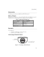
Page 16: ...able 1 1 Battery Charging Accessories Scanners The terminal uses integrated standard range 1 D bar code scanner external scanner with DB9 connector Connecting an External Scanner Figure 1 1 Connecting an External Scanner Accessory Part Number Single Slot Cradle CRD 6100 1000 UBC 2000 6004 xxx Charging and Communications Cable with power supply 25 33665 01 Four Slot Cradle CRD 6100 4000 not yet ava...

Page 17: ... Remove the clear protective tape from the display and the optical connector Save the shipping container for later storage or shipping Inspect all equipment for damage and make sure you have received everything listed on the packing slip If you find anything unsatisfactory or missing contact your authorized customer support representative immediately Miscellaneous Other Accessories A holster and o...

Page 18: ...se in batch applications 6100 or in a Spectrum One network environment PDT 6110 refer to Chapter 3 Batch and Spectrum One Terminal Setup for information on loading the software If this unit is intended for use in a Spectrum24 network environment PDT 6142 or PDT 6146 refer to Chapter 4 Spectrum24 RF Terminal Setup for general information on Spectrum24 ...

Page 19: ...1 6 PDT 6100 Product Reference Guide ...

Page 20: ...cessories Verify that you have the following cradle parts cables and other kits accessories before attempting to mount or connect the cradle Save the shipping container for storing or shipping the cradle Inspect all equipment for damage If anything is damaged or missing call your authorized customer support representative immediately One slot 61XX cradle with spare battery charging slot RS 232 Nul...

Page 21: ...re 2 1 Parts of the Cradle Back View Spare Battery Charging Slot DB 25 Communications Port AC Power Connector Modem Connector available as an option Front View Terminal Slot Connector RJ41 Spare Battery Charging Slot Communications LED Spare Battery Charging LED ...

Page 22: ...port 3 Connect the power jack to the cradle s AC power port 4 Connect the power supply to a line cord 5 Insert the line cord s connector in a standard electrical outlet Connecting the Internal Modem Some cradles use an optional internal modem that communicates at rates of up to 14 400 bps with v 32 bit data compression It can be connected directly to a telephone line through the RJ 11 port shown i...

Page 23: ...iance The terminal s application can control these settings and enable you to view and amend the settings for country region pulse tone dialing or repeat dial timing Incorrectly defining these settings can lead to illegal use of the modem and can create unreliable operation The application developer should consult the Series 3000 Application Programmer s Reference Manual for correct settings Conne...

Page 24: ...l the battery refer to Chapter 6 Maintaining the Terminal Charge the battery refer to Chapter 6 Maintaining the Terminal Load the system files and application s Hardware Requirements Hardware required for performing initialization includes Host PC RS 232 serial null modem cable PDT 6100 terminal Cradle with power supply Refer to Chapter 2 Installing the Hardware for setting up the cradle for commu...

Page 25: ...der function from Command Mode on the PDT 6100 Programs are stored in the terminal s nonvolatile memory NVM also called the application EEPROM For details on SENDHEX refer to the Series 3000 Application Programmer s Manual Other software may be used in place of the SENDHEX program Set up for Initialization 1 Verify that the cradle is connected to the host PC Refer to Chapter 2 Installing the Hardw...

Page 26: ...st through a cradle to program the NVM Initiate Host Communications Software on the PC 1 Power on host computer 2 Start the communication program 3 At a DOS prompt enter the SENDHEX command sendhex pgmname 38400 com2 where In the example baud rate is set to 38400 bps and communications port to COM2 The default values are accepted for the remaining parameters SENDHEX is the command pgmname is the a...

Page 27: ...et Before starting communications refer to Starting Communications on page 3 6 set up the PDT 6100 for loading a HEX image as directed in the following sections Initiate Terminal Communications 1 Boot the PDT 6100 to command mode For the 22 Key terminal Press and hold SEND and 9 Press and release PWR Release SEND and 9 For the 35 Key terminal Press and hold BKSP and SHIFT Press and release PWR Rel...

Page 28: ...it while the NVM is erased When complete the program prompts for the communications parameters 5 Baud Rate The PDT 6100 displays Comm Parameters Baud 5 38400 Scroll through the list using UpArrow or DownArrow When the correct rate is displayed 38400 is recommended press ENTER 6 Data Bits The PDT 6100 displays Comm Parameters Data Bits 7 Press 7 recommended or 8 to specify data bits or scroll throu...

Page 29: ... control option None Xon Xoff or RTS CTS or scroll using UpArrow or DownArrow and press ENTER when the correct value is displayed 9 Go to Starting Communications to continue Starting Communications The PDT 6100 is ready to receive the program from the host PC and displays Comm Parameters Start ENT 1 Press ENTER on the PDT 6100 The PDT 6100 waits a few seconds for the host PC to initiate communicat...

Page 30: ...on is complete the PDT 6100 displays Program loader Status 0000 A status of 0000 all zeros indicates a successful transfer Other status values indicate an error These values are provided in Appendix C Communications Status Codes Ending Communications To return to the Command Mode main menu 1 Press CLEAR on the PDT 6100 2 Power down the PDT 6100 3 Remove the PDT 6100 from the cradle 4 Reboot the PD...

Page 31: ...3 8 PDT 6100 Product Reference Guide ...

Page 32: ...HEX the terminal can also run diagnostic tools Accessing the Flash Disk The flash disk is accessed through a driver FLASHDSK SYS which makes the flash disk appear to a program as another disk drive E The drive has characteristics of fast reading but slow writing for example even for the smallest files the write process takes 3 4 seconds These characteristics make it ideal for files that are writte...

Page 33: ...h minor changes as detailed in this chapter If your requirements are more advanced refer to the Spectrum24 Network Terminal Technical Reference Guide p n 70 20193 XX for more information on the Spectrum24 RF network SLAODI COM the Symbol provided ODI driver and the configuration file setups required for various platforms Refer to the Spectrum24 Terminal Setup and Utilities Reference Guide p n 72 5...

Page 34: ...how to operate a PDT 6100 terminal including Powering the terminal on off Booting the terminal Adjusting the display s contrast Entering data using the keyboard Entering data through the integrated scanner Communicating with other devices using the Charging and Communications Cable ...

Page 35: ... or initialize either the program or data For more information on initialization refer to Chapter 3 Batch and Spectrum One Terminal Setup Normal Power Note Charge the NiMH battery before use To power the terminal on or off press PWR Automatic Power Depending on the application a number of other events may turn a terminal on or off Power On The system powers on when a key other than PWR is pressed ...

Page 36: ...er back on does not solve the problem To recover the data held in memory perform a Warm Boot refer to Booting the Terminal on page 5 4 Restarting After a Forced Power Off If an operator is forced to power down a terminal because of defective software the System Administrator should restart the system using the warm or cold boot procedures in the following section Note Do not use the power key to r...

Page 37: ...d hold Down Arrow and Period Press and release PWR Release Down Arrow and Period For the 35 Key terminal Power the terminal off Press and hold F and J Press and release PWR Release F and J For the 46 Key terminal Power the terminal off Press and hold 4 and 5 Press and release PWR Release 4 and 5 The terminal displays a copyright message RAM size expanded memory RAM size etc depending on the system...

Page 38: ...reside in NVM Contents of RAM are lost To perform a cold boot For the 22 Key terminal Power the terminal off Press and hold Up Arrow 4 and ENTER Press and release PWR Release Up Arrow 4 and ENTER For the 35 Key terminal Power the terminal off Press and hold SPACE FUNC and Up Arrow Press and release PWR Release SPACE FUNC and Up Arrow For the 46 Key terminal Power the terminal off Press and hold A ...

Page 39: ...s listed in Related Publications at the beginning of this manual Boot to Command Mode Command Mode provides functions for Running the Self Test program to verify that the hardware is operating properly refer to Chapter 7 Error Recovery and Troubleshooting Performing a Memory Transfer to upload data from a terminal to a host system refer to Chapter 7 Error Recovery and Troubleshooting Performing a ...

Page 40: ...light on or off press the following keys in sequence Func then L Lamp The backlight also turns off when a terminal is powered off or when a timeout set by the application occurs Display Contrast The LCD display contrast is adjustable making the display more readable in different lighting conditions at various temperatures with different attachments and at other viewing angles To increase contrast ...

Page 41: ...hift Alpha Ctrl and Func used individually or in combination determine which character or special function the character keys produce Using the Keyboard Except for during boot operations the terminal expects the operator to press keys one at a time If ERR3000 is loaded and if two or more keys are pressed simultaneously the system indicates a Double Key error The keyboard also has an optionally con...

Page 42: ...g the PDT 6100 Series Figure 5 2 PDT 6100 Standard 35 Key Keyboard Figure 5 3 PDT 6100 Standard 46 Key Keyboard CTL A B C D E F G H I J K L M N O P Q R S T U V W X Y Z CLR FNC SHF BSP 0 ENTER 1 2 3 4 5 6 7 8 9 SCAN ...

Page 43: ...ctive only when held down The Alpha key on the keyboard affects all succeeding character keys until Alpha is pressed again The other modifier keys affect only the next character key Refer to Appendix B Keyboard Layouts for the characters and operations produced by pressing a sequence of modifier keys on the standard terminal keyboards These key assignments can be changed by an application Refer to...

Page 44: ...haracter at a time Information erased this way cannot be recovered This key is also used to produce a break by pressing CTL BKSP PWR Power PWR Power Turns the terminal on and off CLEAR CLR Clear Partially or completely escapes from an application level or screen CLR also clears all data typed from the display SHIFT SHF Shift Accesses the shifted keyboard ENTER ENTER ENTER Places entered data into ...

Page 45: ...figure To use the integrated laser scanner 1 Power on the system and scanner by pressing PWR or the scanner trigger 2 Lift up and turn the scan element on the top of the terminal to the preferred orientation for scanning refer to Figure 5 4 The scan head turns only toward the back of the terminal Figure 5 4 Positioning the Integrated Scanner 3 Lock the scan head in position facing the side of the ...

Page 46: ... you wish to scan The scanner turns toward the back of the 6100 3 Point the PDT 6100 at the bar code and press the scan bar or a side trigger Figure 5 5 Scanning a Bar Code 4 Ensure that the scan beam crosses all bars and spaces on the symbol as shown below Right Wrong 5 Hold the scanner farther away for larger symbols and closer for symbols with bars that are close together 6 The LED turns from y...

Page 47: ...e 5 6 Scanning Angle and Specular Reflection Range Any scanning device decodes well over a particular working range minimum and maximum distances from the bar code This range varies according to bar code density and scanning device optics Scanning within range brings quick and constant decodes scanning too close or too far away prevents decodes You need to find the right working range for the bar ...

Page 48: ...f bar code symbols Figure 5 7 PDT 6100 Decode Zone In cm 0 0 5 12 7 10 25 4 15 38 1 20 50 8 25 63 5 30 76 2 Minimum distance determined by symbol length and scan angle 0 5 10 15 5 10 In cm W i d t h o f F i e l d Depth of Field Note Typical performance at 68 F 20 C on high quality symbols 15 5 mil 4 8 2 2 7 5 mil 6 2 1 8 SE 900 STANDARD 100 UPC 13 0 2 0 20 mil 20 0 40 mil 25 0 55 mil 26 0 0 12 7 2...

Page 49: ...1 Set up the cradle as described in Connecting the Cables on page 2 3 or in the CRD 6100 Quick Reference Guide 2 Place the 6100 s base in the cradle Press the top of the 6100 against the cradle back until it is firmly seated The terminal s Charging LED flashes yellow and then lights solid yellow when the terminal is securely placed in the cradle 3 Start the communications program on the host and t...

Page 50: ... a Symbol Spectrum24 RF network The Status LED indicates the state of the 6100 s connection to either of the RF networks Refer to the network documentation for more information on operating the PDT 6100 in the specific RF environment Off indicates that the radio is working and associated with an access point Spectrum24 or base station Spectrum One The Status LED indication of RF activity is presen...

Page 51: ...printer use the CCC or the appropriate printer cable The following directions apply to the CCC 1 Plug the CCC s 10 pin RJ 41 connector into the PDT 6100 terminal s serial port refer to Figure 5 9 2 Plug the DB 9 connector in the communications port on the printer 3 Start the communications program ...

Page 52: ...ture battery age and data collection method Uses and operating conditions which affect battery life are scanning power save mode radio communications backlighting very high operating temperatures very low operating temperatures The approximate battery life between charges is summarized in Table 6 1 Note that these values vary with the application Applications involving radio communications shorten...

Page 53: ...Y message appears and the system powers off Replace or recharge the battery before attempting to use the terminal If the battery is not immediately recharged or replaced data may be lost Battery life varies between 500 1000 charge discharge cycles This variation depends on the depth of discharge In general replace batteries which exhibit less than 80 of their total rated capacity Battery Type Inpu...

Page 54: ...ides sufficient power to preserve memory contents for approximately 15 minutes while batteries are replaced The supercap does not provide enough power to operate the terminal On receiving a low battery message replace or recharge the primary batteries immediately Replacement Batteries A rechargeable 1500 mAh NiMH battery pack p n 21 33061 01 can be ordered from Symbol Technologies 33222010 eps ...

Page 55: ... latch counterclockwise and remove the battery compartment door Figure 6 1 Removing the Battery Compartment Door 2 Lift the battery pack out 3 Slide a NiMH battery pack in the compartment with the contacts facing inside the compartment and the tab facing the top of the compartment Figure 6 2 Figure 6 2 Inserting the NiMH Battery Pack Tab Contacts ...

Page 56: ...tery Using the CRD 6100 To charge the NiMH battery in the PDT 6100 1 Seat the PDT 6100 in a CRD 6100 connected to a power source Figure 6 4 Seating the PDT 6100 in the CRD 6100 2 The PDT 6100 s Charging LED flashes yellow at the start lights solid yellow while the battery is charging and lights solid green when the battery is fully charged The charging time required is approximately 2 5 hours ...

Page 57: ... connect the 6100 and the CCC 1 Plug the CCC s 10 pin RJ41 connector in the 6100 s base 2 Plug the connector from the 12V power supply in the CCC s power input jack power supply p n 50 14000 086 3 Connect the power supply s connector to a power line cord Figure 6 5 Connecting the CCC 4 Connect the power line cord to a wall outlet Batteries recharge in 2 5 hours 33222013 eps ...

Page 58: ...ttery is first inserted The LED lights solid yellow to indicate the spare battery is charging and switches to solid green when the battery is charged The spare battery recharges in 2 5 hours 4 Remove the spare battery and place it in the PDT 6100 or leave it in the cradle for temporary storage To remove the battery grip on either side of the battery and lift it out of the charging slot Note The sp...

Page 59: ...ampened with a mild cleaner such as soap and water Do not use abrasive paper cloth or abrasive corrosive cleaners Wipe the entire terminal except for the scanner window with the damp cloth Clean the keypad and scanner triggers Wipe the scanner window periodically with a lens tissue or other material suitable for cleaning optical material such as eyeglasses Caution Do not pour spray or spill any li...

Page 60: ...mary batteries for longer than 15 minutes When you remove the terminal from storage without the battery pack reset the real time clock Refer to the Series 3000 Application Programmer s Reference Manual or Series 3000 Application Programmer s Guide for specific instructions ...

Page 61: ...6 10 PDT 6100 Product Reference Guide ...

Page 62: ...g memory transfer Scanning problems Error Messages If ERR3000 is loaded in the system configuration the terminal displays the following messages to indicate error conditions that affect system performance A message is usually accompanied by one or more beeps after which the system returns to its previous status The application can change the actual wording of the messages or disable messages The m...

Page 63: ...d later in this chapter After downloading new software warm boot the terminal as described in Chapter 5 Operating the PDT 6100 Series Boot Failure Messages During a cold boot the system briefly displays a status line for each driver as it loads in the format 0 Driver Message Explanation Double Key Error Two or more keys were pressed at the same time This does not include boot sequences refer to Ch...

Page 64: ...roubleshooting Spectrum24 Terminals Problem Explanation Action Out of range Terminal is out of the Access Point s range If you move the terminal during initialization the terminal may be out of range of the AP and unable to complete the initialization process Move back in range and repeat the initialization process Startup process fails Boot server type BOOTP or DHCP doesn t exist Verify that the ...

Page 65: ...s 3 Highlight Screen Test and press Enter Self Test Summaries The Self Test is divided into five functions or screens Config Screen 1 Reports the terminal type and version time date main battery status current power source and status of the serial ports when a loopback connector is used Config Screen 2 Reports information on the keyboard and display If a laser scanner is attached the test reports ...

Page 66: ...ey the corresponding key code is displayed on the top row to the right of the test name Table 7 3 Table 7 4 and Table 7 5 list the codes for the 22 key 35 key and 46 key keyboards respectively Table 7 3 22 Key Keyboard Test Codes Key Test Code Key Test Code Left Arrow 00 6 14 Right Arrow 01 5 13 Up Arrow 03 4 12 Down Arrow 04 3 17 FUNC 05 2 16 SEND 06 1 15 07 0 19 9 11 18 8 10 ENTER 20 7 09 ...

Page 67: ...7 4 35 Key Keyboard Test Codes Key Test Code Key Test Code Alpha 0 M 18 Space 1 N 19 Shift 2 9 22 Func 4 8 21 Ctrl 5 7 20 A 6 6 26 B 7 5 25 C 8 4 24 D 9 3 30 E 10 2 29 F 11 1 28 G 12 0 32 H 13 Backspace 27 I 14 X 31 J 15 Z 33 K 16 Enter 34 L 17 ...

Page 68: ...y Test Code Key Test Code CONTROL 3 V 26 SHIFT 2 W 27 A 5 X 28 B 6 Y 29 C 7 Z 30 D 8 Up Arrow 33 E 9 Down Arrow 34 F 10 0 44 G 11 1 41 H 12 2 42 I 13 3 43 J 14 4 38 K 15 5 39 L 16 6 40 M 17 7 35 N 18 8 36 O 19 9 37 P 20 BKSP 31 Q 21 SPACE 47 R 22 FUNC 1 S 23 32 T 24 ENTER 45 U 25 ...

Page 69: ...yze an application using tools provided in the Series 3000 Application Development Kit and described in the Series 3000 Application Programmer s Reference Manual Hardware Setup 1 Turn OFF the terminal and host PC Disconnect or unplug the cradle if used Caution Always turn off the terminal before attaching or removing cables 2 Connect the terminal and host PC using the communications charger cable ...

Page 70: ...Power on the host PC 5 Plug in the cradle if used Figure 7 2 Cradle Connections for MemoryTransfer Set Communications Parameters Host 1 Start the Communications program on the host PC 2 Set up the host communication parameters these parameters must match the terminal s parameters At the DOS prompt on the host enter RCVHEX filename hex baud rate comport Typical parameters are 38400 bps 7 bit data O...

Page 71: ...to the range verification screen step 7 If you select Range the screen displays RAM Use Arrow Keys Start End 00000 9FFFF 4 Specify a range of RAM by setting the Start and End addresses Use RightArrow and LeftArrow to move the cursor to the digit to be changed Use UpArrow and DownArrow to change the values Type a range and press Enter 5 Specify a range of NVM to transfer Choose All or None 6 If the...

Page 72: ... 8 and press Enter Note If you select 8 data bits the program selects No parity and skips the next screen 10 Specify parity type Use UpArrow and DownArrow to display a parity option or press the first letter of a parity option Even Odd None Space or Mark and press Enter 11 Set flow control Use UpArrow and DownArrow to display the flow control options or press the first letter of an option None Xon...

Page 73: ...ving difficulties with your internal modem please check the following before returning your product Connection to the telephone network is correct Any necessary special requirements such as dialing 9 and ignoring dial tone have been considered in the event of using a PBX Firmware settings described in the Series 3000 Application Programmer s Guide have been configured correctly Scanning Problems W...

Page 74: ...bits etc are set properly for the receiving device The laser does not activate You may have exceeded the allowable amount of scanning activity within the limits of your laser class of operation in this case wait for a short interval before scanning again You may be scanning in an inappropriately hot environment If so remove the equipment from that environment or allow the laser to cool down ...

Page 75: ...7 14 PDT 6100 Product Reference Guide ...

Page 76: ...erial Devices The RJ41 connector is located in the base of the terminal Table A 1 RJ 41 Connector Pin Signal Description 1 DSR Data Set Ready input 2 DCD Data Carrier Detect input 3 RXD Received Data input 4 RTS Request to Send output 5 TXD Transmit Data output 6 Power 12VDC 7 RING Ring input 8 GND Ground 9 CTS Clear to Send input 10 DTR Data Terminal ready output ...

Page 77: ...A 2 PDT 6100 Product Reference Guide ...

Page 78: ...uence As explained in Chapter 5 these key definitions can be changed by the application pro gram The captions indicate what sequence of modifier keys produce the keyboard Figure B 1 shows a typical key and the location of its associated Scan Code ASCII Value and Printable Character or Logical Key Sequence Figure B 1 Key Representation 0 11 48 Scan Code decimal ASCII Value decimal Printable Charact...

Page 79: ...77 00 97 00 78 43 12 45 1 27 72 00 80 00 8 55 9 56 10 57 5 52 6 53 7 54 2 49 3 50 4 51 11 48 52 46 28 13 22 Key Keyboard 22 Key Unmodified Keyboard FUNC E N T E R SCAN BACK LIGHT LIGHTER SCREEN DARKER SCREEN F7 F8 F9 F4 F5 F6 F1 F2 F3 F10 100 00 102 00 101 00 65 00 66 00 67 00 62 00 63 00 64 00 59 00 60 00 61 00 68 00 28 13 22 Key Function Key Modified Keyboard ...

Page 80: ... 40 39 27 93 26 91 55 42 13 61 43 92 51 44 53 47 78 43 39 59 72 00 77 00 75 00 1 27 80 00 9 56 8 55 57 32 58 00 10 57 6 53 5 52 42 00 97 00 7 54 3 50 2 49 29 00 28 13 4 51 11 48 12 45 14 8 52 46 35 Key Keyboard 35 Key Unmodified Keyboard ...

Page 81: ...82 42 00 97 00 20 84 47 86 22 85 29 00 28 13 17 87 21 89 45 88 14 8 44 90 18 69 30 65 _ 40 34 27 185 13 43 43 124 51 60 53 63 78 43 39 58 72 56 77 54 75 52 1 27 80 50 9 42 8 38 57 32 58 00 10 40 6 37 5 36 42 00 97 00 7 94 3 64 2 33 29 00 28 13 4 35 11 41 12 95 14 8 52 62 55 00 26 123 35 Key Alpha Key Modified Keyboard 35 Key Shift Key Modified Keyboard ...

Page 82: ...0 97 00 20 20 47 22 22 21 29 00 28 13 17 23 21 25 45 24 00 3 44 26 18 5 30 1 40 39 41 96 13 61 79 0 51 44 102 78 43 39 59 73 00 71 00 1 27 81 00 66 00 65 00 57 9 58 00 67 00 63 00 62 00 42 00 97 00 64 00 60 00 59 00 56 00 28 13 61 00 68 00 101 83 00 102 101 82 00 35 Key Control Key Modified Keyboard 35 Key Function Key Modified Keyboard ...

Page 83: ...00 31 00 19 00 42 00 97 00 20 00 47 00 22 00 56 00 17 00 21 00 45 00 44 00 18 00 30 00 41 26 101 13 43 79 49 51 60 102 78 43 39 58 73 57 71 55 1 27 81 51 91 00 90 00 15 00 58 00 92 00 88 00 87 00 42 00 97 00 89 00 85 00 84 00 56 00 28 13 86 00 93 00 101 83 46 102 82 48 35 Key Alt Key Modified Keyboard 35 Key Shift Func Modified Keyboard ...

Page 84: ... 58 00 102 00 98 00 97 00 42 00 97 00 99 00 95 00 94 00 56 00 96 00 103 00 101 102 101 102 111 00 110 00 58 00 112 00 108 00 107 00 42 00 97 00 109 00 105 00 104 00 56 00 106 00 113 00 101 102 101 35 Key Ctrl Func Modified Keyboard 35 Key Alt Func Modified Keyboard ...

Page 85: ... r s t u v w x y z CLR FNC SHF BSP 0 ENTER 1 2 3 4 5 6 7 8 9 SCAN 29 00 30 97 48 98 46 99 32 100 01 27 18 101 33 102 34 103 35 104 23 105 36 106 37 107 38 108 50 109 49 110 24 111 25 112 16 113 19 114 31 115 20 116 22 117 47 118 17 119 45 120 21 121 44 122 08 55 09 56 10 57 05 52 06 53 07 54 02 49 03 50 04 51 52 46 11 48 28 13 42 00 14 08 72 00 80 00 46 Key Keyboard 46 Key Unmodified Keyboard ...

Page 86: ...06 37 07 94 02 33 03 64 04 35 52 62 11 41 28 13 42 00 14 08 72 56 80 50 CTL A B C D E F G H I J K L M N O P Q R S T U V W X Y Z CLR FNC SHF BSP ENTER SCAN 1 2 3 4 5 6 7 8 9 0 29 00 30 65 48 66 46 67 32 68 01 27 18 69 33 70 34 71 35 72 23 73 36 74 37 75 38 76 50 77 49 78 24 79 25 80 16 81 19 82 31 83 20 84 22 85 47 86 17 87 45 88 21 89 44 90 08 55 09 56 10 57 05 52 06 53 07 54 02 49 03 50 04 51 52 ...

Page 87: ... 49 14 24 15 25 16 16 17 19 18 31 19 20 20 22 21 47 22 17 23 45 24 21 25 44 26 07 30 03 00 28 10 00 03 141 00 145 00 ALT e f g z CLR FNC CAPLK SPACE SCAN BACK LIGHT DARKER SCREEN LIGHTER SCREEN HOME END INS DEL PAGE UP PAGE DOWN F7 F8 F9 F4 F5 F6 F1 F2 F3 F10 56 00 78 43 74 45 53 47 01 27 18 101 33 102 34 103 41 96 13 61 43 92 12 45 26 91 27 93 39 59 71 00 79 00 40 39 51 44 53 47 82 00 83 00 73 00...

Page 88: ...0 85 00 86 00 81 51 93 00 13 43 57 32 75 52 77 54 CTL SCAN Alt A Alt B Alt C Alt D Alt E Alt F Alt G Alt H Alt J Alt K Alt L Alt M Alt N Alt O Alt I Alt P Alt Q Alt R Alt S Alt T Alt U Alt V Alt W Alt X Alt Y Alt Z FNC Alt 7 Alt 8 Alt 9 Alt 6 Alt 3 Alt 2 Alt 5 Alt 4 Alt 1 Alt 0 30 00 48 00 32 00 18 00 33 00 34 00 35 00 23 00 36 00 37 00 50 00 49 00 24 00 25 00 16 00 19 00 31 00 20 00 22 00 47 00 1...

Page 89: ... 28 12 31 26 27 27 29 119 00 117 00 132 00 44 26 100 00 101 00 102 00 97 00 98 00 99 00 94 00 95 00 96 00 103 00 55 00 116 00 115 00 57 32 1 27 118 00 SCAN Alt E Alt F Alt G Alt Alt Alt Z Alt F7 Alt F8 Alt F9 Alt F6 Alt F3 Alt F2 Alt F5 Alt F4 Alt F1 Alt F10 BACK LIGHT DARKER SCREEN LIGHTER SCREEN SPACE Alt 18 00 33 00 34 00 130 00 131 00 44 00 110 00 111 00 112 00 107 00 108 00 109 00 104 00 105 ...

Page 90: ...s of four hexadecimal digits which indicate whether or not the transfer was successful and if not the source of the communications error A status code of 0000 indicates success any other code indicates failure Table C 1 lists the failures associated with the status codes The values are additive ...

Page 91: ...e not present 0020 Data Set Ready or Carrier Detect not detected on open 0040 Lost DSR while receiving 0080 ABORT key hit during comm 0100 Insufficient NVM for image 0200 Illegal Intel hexadecimal record 0400 Unsupported Intel record 0600 NVM EEPROM failed to erase 0800 Receive time out error 1000 Control start character time out 2000 Clear To Send inactive time out error 4000 Receive buffer full ...

Page 92: ...conditions are listed in Table Table D 1 Table D 1 Environmental Specifications Condition Range Operating Temperature 4 to 122 F 0 to 40 C Storage Temperature 40 to 158 F 40 to 60 C Humidity Operating 5 to 95 non condensing 50 C for 168 hours Altitude Up to 10 000 feet ...

Page 93: ...D 2 PDT 6100 Product Reference Guide ...

Page 94: ...al AP See Access Point Application Programming Interface API An interface by means of which one software component communicates with or controls another Usually used to refer to services provided by one software component to another usually via software interrupts or function calls ASCII American Standard Code for Information Interchange A 7 bit code representing 128 letters numerals punctuation m...

Page 95: ...without adding extra symbol elements Code 3 of 9 Code 39 A versatile and widely used alphanumeric bar code symbology with a set of 43 character types including all uppercase letters numerals from 0 to 9 and 7 special characters and space The code name is derived from the fact that 3 of 9 elements representing a character are wide while the remaining 6 are narrow Code 93 An industrial symbology com...

Page 96: ...hannels to achieve spread spectrum compliance Stations that use frequency hopping change their communications frequency at regular intervals A hopping sequence determines the pattern at which frequencies are changed Messages take place within a hop Refer to Hopping Sequence and Spread Spectrum FTP See File Transfer Protocol Hopping Sequence A set of random frequencies designed to minimize interfer...

Page 97: ...sing them to reflect light outside according to their bias They use little electricity and react relatively quickly They require external light to reflect their information to the user MU Mobile Unit NCU Network Control Unit Null Modem A special cable that allows direct connection of two DTE Data Terminal Equipment devices by making each perceive the other as a DCE Data Communications Equipment de...

Page 98: ...t sequencing Spread Spectrum A technique for uniformly distributing the information content of a radio signal over a frequency range larger than normally required for robust transmission of data Spreading the signal without adding additional information adds significant redundancy which allows the data to be recovered in the presence of strong interfering signals such as noise and jamming signals ...

Page 99: ...e of the standard network protocols that were originally used in UNIX environments but are now used in many others The TCP governs sequenced data the IP governs packet forwarding TCP IP is the primary protocol that defines the Internet TFTP Trivial File Transfer Protocol TSR Refer to Terminate and Stay Resident UPC Universal Product Code A relatively complex numeric symbology Each character consis...

Page 100: ...eable batteries 1 3 6 1 scanners 1 3 adjusting the display 5 7 Alpha key 5 10 ALPHA key default 5 12 ALPHA trigger 5 12 ALT key 5 10 B backlight 5 7 Backspace Key 5 11 batch loading applications 3 1 loading system files 3 1 batch environment 3 2 loading an application 3 3 set up for software download 3 2 batteries backup 6 3 chargers 1 3 charging 6 5 charging a spare in the cradle 6 7 charging tip...

Page 101: ... scanner 1 3 connectors pin assignments A 1 Control key 5 10 conventions notational vii cradle connecting 2 3 description 2 1 parts of 2 2 cradles single slot 1 3 CRD 6100 accessories 2 1 charging a spare battery 6 7 charging the battery 6 5 connecting the cables 2 3 power supply 2 1 required parts 2 1 cursor shapes 6 2 D display adjusting contrast 5 7 backlight 5 7 darker 5 7 lighter 5 7 display ...

Page 102: ...ow Power message 6 2 M maintenance cleaning 6 8 memory transfer 5 6 7 8 ending communications 7 12 initiating transfer to host 7 11 selecting a range 7 10 selecting communications parameters 7 11 status 7 12 messages Double Key Error 5 8 driver loading 7 3 Low Power 6 2 modifier keys 5 10 N network options Spectrum One 1 4 Spectrum24 1 4 NiMH battery charging 6 5 installing 6 4 NiMH battery pack 6...

Page 103: ...sing the integrated scanner 5 12 working range 5 14 scanning integrated scanner 5 12 scanning angle 5 14 screen display verification see self test self test 5 6 7 4 battery condition 7 4 display information 7 4 EMS available 7 4 exiting 7 8 keyboard status 7 4 power source 7 4 RAM available 7 4 real time clock verification 7 4 screen display verification 7 4 serial port status 7 4 terminal type 7 ...

Page 104: ...er function 3 2 sendhex command 3 2 terminal type see self test test codes 22 key 7 5 35 key 7 6 46 key 7 7 testing memory see self test troubleshooting 7 2 applications 7 8 memory transfer 7 8 scanning 7 12 Spectrum24 terminals 7 3 U UBC 2000 6 7 W warm boot description 5 4 ...

Page 105: ...Index 6 PDT 6100 Product Reference Guide ...

Page 106: ...___ please include revision level How familiar were you with this product before using this manual Did this manual meet your needs If not please explain _________________ _________________________________________________________________ What topics need to be added to the index if applicable _________________ _________________________________________________________________ What topics do you feel...

Page 107: ......

Page 108: ...70 33222 02 Revision A June 2001 Symbol Technologies Inc One Symbol Plaza Holtsville N Y 11742 1300 PDT 6100 Series Product Reference Guide ...

Reviews: