background image

Remote RTD Module Comm Port (Port 1, A1 & B1)

Remote RTD Module Address

 - can be set from 16 to 23.

R E M O T E

R T D

( P O R T

1

)

R T D

A D D R E S S :

1 6

The RTD Address must match the address selected on the RTD module.

Remote RTD Module Communication Parameters

R T D

B A U D :

1 9 2 0 0

P A R I T Y : N

S T O P :

1

The RM-2000-RTDW can communicate with an RTD module using 300, 600, 1200,
2400, 9600, 14400, 19200 or 28800 baud; even, odd or no parity; and 0, 1 or 2 stop bits.
If using a Benshaw Remote RTD module, select 19200 baud, no parity, and 1 stop bit.

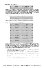
Model and Voltage Multiplier

M O D E L

:

7 7 7

V O L T A G E

M U L T

:

1

Model Number

The Model Number setting should match the model number of the 777 monitored by the
RM-2000.

Voltage Multipllier

Voltage Multiplier should be set to 1 unless the 777 is powered by potential transformers
(PTs). This multiplier is used to scale the voltage readings up to the actual line voltages
being monitored.

Model 777 Power Factor Correction

M O D E L

7 7 7 M V

W I T H

O N L Y

1

P . T

.  ?

:

N O

If the Model 777-MV (Medium Voltage) is installed with only ONE potential transformer
(PT), set this function to YES—the RM-2000-RTDW will adjust the power factor to
correct the Power, kVARs, and Energy Usage values. Be sure to check the Model 777-
MV installation instructions to keep the proper relationship between PT and CT
connections.

LCD Control and UC Alarm Control

A U T O

L C D

D I M

:

Y E S

A L A R M

O N

U / C

:

Y E S

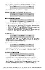
LCD Control

If the Auto LCD Dim option is set to NO, the backlighting of the LCD will remain on all the
time. If the option is set to YES, the backlighting will automatically turn off 2 minutes after
the last button is pressed.

UC Alarm Control

This setting is commonly used in pumping applications. If a well runs dry, the Model 777
will shut down the motor because of  an undercurrent condition. Since this may occur
frequently in pumping applications, the undercurrent faults can fill up the last four faults
of the RM-2000-RTDW. If you do not want the fault screen to pop up on the RM-2000-
RTDW when an undercurrent fault is detected, set this field to “NO”. This allows the last
four faults to keep track of other, unexpected faults.

Phone: 800.894.0412 - Fax: 888.723.4773 - Web: www.clrwtr.com - Email: info@clrwtr.com

Summary of Contents for Motor Saver RM-2000-RTDW

Page 1: ...of a panel or MCC The RM 2000 RTDW displays the following motor information Real time line currents average current and current unbalance Current to ground Line to line voltages average voltage and voltage unbalance Instantaneous power Power factor Last four faults All programmed 777 settings Remaining restart delay times 8 RTD temperatures Warning settings The RM 2000 RTDW is also equipped with a...

Page 2: ...n to the date and time of the fault Historical data the RM 2000 RTDW can display historical data about the motor being monitored by the Model 777 such as the total number of starts the number of trips and the date and time of the last 10 starts Installation Panel mounting a model 777 is often mounted inside a motor control panel and its display is not visible The RM 2000 RTDW can be mounted on the...

Page 3: ...ould include at least 120VAC control power one set of communication wires to the 777 and ground wire to case ground on the panel NOTE When connecting a Benshaw remote RTD module terminal A of the RTD module must be connected to B1 of the RM 2000 B must be connected to A1 5 It is important to have the A phase of the breaker connected to L1 on the 777 B phase to L2 and C to L3 Equally important is t...

Page 4: ...CON T EQ LIST ED 784X A B S V R R REMOTE RTD MODULE REMOTE RTD MODULE MODEL RS485MS 2W 115VAC L1 NO2 C2 NC2 NO1 C1 NC1 L2 A1 A B B1 REMOTE RESET GROUND FAULT MONI TOR RTD ALARM WARNING ALARM GF C RR SETPOINT SETUP CHANGE SETUP F AULT ENTER MODE STOP SCROLL RUN RESET COMM STATUS RUN REAL TIME FAULT HISTORY DISPL AY PROGRAM RD2 UCTD CUB LV MULT UC OC HV VUB RD1 TC GF RUN RU ADDR RD3 RF MODE SELECT L...

Page 5: ...e Model 777 exceeds 100 feet or if the twisted pair cable is in a noisy environment 120 terminating resistors should be connected at both the RM 2000 RTDW across A1 and B1 and also at the Model 777 across A and B of the RS485MS 2W module In addition the shield of the twisted pair cable should be tied to the RM 2000 RTDW s ground connection labeled GND with a single 100 resistor Unlike the port pow...

Page 6: ...ure from RTDs calculated power factor and power consumption and total number of starts and trips FAULT HISTORY displays detailed information about the last 4 faults that caused the Model 777 to trip It also displays the last 10 starts the length of time the motor has been running and the date time and length of the minimum time the motor was off SETPOINT displays the parameters programmed into the...

Page 7: ...such as high or low voltage Look at the pending fault screen in the REAL TIME mode to view the existing fault condition TROUBLESHOOTING COMMUNICATION LOSS If the RM 2000 RTDW loses communications with the Model 777 or the RTD module the green COMM STATUS LED will blink If communication is lost with both devices the LED will be off Any screens with data read from these devices will contain asterisk...

Page 8: ...mmed with a voltage multiplier equal to the PT ratio The voltage displayed on the RM 2000 RTDW will be higher than the voltage displayed on the 777 but will be consistent with the actual voltage Calculated Current and Voltage Unbalance C U R R U N B A L A N C E 3 V O L T U N B A L A N C E 2 Restart delays RD1 RD2 and RD3 R E S D E L A Y R D 2 0 M R D 1 0 S R D 3 0 M RD1 power up and rapid cycle de...

Page 9: ...del to 601 in the CHANGE SETUP mode This allows the Frequency information of the Model 601 to be displayed on this screen instead of Average Voltage and Average Current Power and KVARS displays consumed motor power in kW and reactive power in kVARS P O W E R K W 1 2 1 K V A R S 0 6 4 RTD Inputs displays temperature measurements from the 8 RTDs R T D 1 7 0 C R T D 2 1 0 0 C Input Status Bits displa...

Page 10: ...on The RM 2000 RTDW will store detailed information about the last 4 faults The fault information may be cleared by the CLEAR FAULTS option in the CHANGE SETUP mode NOTE When a fault occurs the RM 2000 RTDW will jump to the FAULT HISTORY mode and display the Fault 1 screen To return to the previous mode press ENTER Fault Description Date Time fault 1 is the most recent fault 4 is the oldest F A U ...

Page 11: ...h of time between the last motor start and stop R U N T I M E 1 D A 2 0 H R S 2 8 M I N 5 4 S E C Minimum Off Time Date of Minimum Off Time date and time of the start following the Minimum Off Time Minimum Off Time the minimum length of time the motor was off M I N O F F T I M E 1 M I N 2 S E C Very short times may signify a motor was not allowed to cool down before restarting indicating a program...

Page 12: ... G R N D F A U L T 1 2 0 A Restart Delays RD1 RD2 RD3 settings R E S D E L A Y R D 2 3 0 M R D 1 0 S R D 3 2 0 M RD1 rapid cycle delay RD2 restart delay after all faults except undercurrent RD3 restart delay after an undercurrent fault NOTE This screen shows the setpoint for each restart delay not the time remaining Trip Class and Under Current Trip Delay TC and UCTD settings T R I P C L A S S 1 0...

Page 13: ...E L A Y O F F The command line allows you to do several things Turn off on slave communication watchdog Send an off or reset command to the 777 Lock unlock network programming prevents allows 777 parameter setting changes Clear run hours Clear last fault Model and Software M o d e l 7 7 7 S o f t w a r e R e v 2 5 3 8 SETUP MODE The SETUP mode displays parameters that affect the operation of the R...

Page 14: ... T O P 1 The RM 2000 RTDW can communicate on a host network using 300 600 1200 2400 9600 14400 19200 or 28800 baud even odd or no parity and 0 1 or 2 stop bits Network Watchdog N e t w o r k W a t c h d o g D I S A B L E D An upstream communication watchdog occurs when no upstream messages are received for 10 seconds Another watchdog will not occur and no watchdog actions will be taken again until...

Page 15: ...he Model 777 MV Medium Voltage is installed with only ONE potential transformer PT set this function to YES the RM 2000 RTDW will adjust the power factor to correct the Power kVARs and Energy Usage values Be sure to check the Model 777 MV installation instructions to keep the proper relationship between PT and CT connections LCD Control and UC Alarm Control A U T O L C D D I M Y E S A L A R M O N ...

Page 16: ...ntacts as soon as the voltage fault goes away The RUN RESET button is currently non functioning on the RM 2000 RTDW Therefore the Starting with Voltage Errors screen and functionality is not applicable Type of Events to Track L O G M T R S T A R T S Y E S M T R S T O P S Y E S L O G R M P W R O N N O R M P W R L O S N O L O G C O M M O N N O C O M M L O S S N O The RM 2000 RTDW will track up to 10...

Page 17: ...x V H V W r n x x x x x x x x x V C U B S e t P t x x x C U B W r n x x x x x x x x x x V U B S e t P t x x x V U B W r n x x x x x x x x x x Warning levels can be set as a percentage of the programmed limits for nominal voltage full load current current unbalance and voltage unbalance the setpoints for each parameter are displayed but cannot be changed on these screens Each warning level can be s...

Page 18: ... in the REAL TIME mode and you can clear the fault information displayed in the FAULT HISTORY mode Clear Events Minimum Off Time C L E A R E V E N T S N O C L E A R M I N O F F N O In the CHANGE SETUP mode CLEAR EVENTS will allow you to clear the 10 starting events The CLEAR MIN OFF option allows you to clear the date and time of last start the run time the date time of the Minimum Off Time and th...

Page 19: ...until both SETPOINT and CHANGE SETUP LEDs illuminate To change SETUP parameters press the MODE button until SETUP and CHANGE SETUP LEDs illuminate In the CHANGE SETUP mode a and will indicate the selected parameter Use the SCROLL UP and SCROLL DOWN buttons to move through the parameters To change the value or a parameter press the CHANGE SETUP UP and DOWN buttons When a value is changed a will app...

Page 20: ...nts at time of trip Output Relays Two independent electro mechanical Form C SPDT Contact Material Silver Tin Oxide Pilot Duty Rating 240VA 120VAC General Purpose Rating 5A 120VAC Environment Class of Protection NEMA 3R Ambient Operating Temperature 20 to 70 C Ambient Storage Temperature 30 to 70 C Humidity Up to 85 non condensing Enclosure Dimensions 6 1 L x 6 5 W x 1 1 D Weight 1 2 lbs Material B...

Reviews: